Document No: C-41-02490-9
31
5. Installation
This chapter describes precautions during sensor installation.
The UST can be fixed to a surface using either the back mounting plate or the bottom mounting plate and
each plate provided with two screw holes. This mounting plate is used as a frame ground (FG). Mount the
sensor on a stable structure.
In the case of using the back mounting plate. 2 M4 screw holes are available (screw depth 6mm).
In the case of using the bottom mounting plate, 2 M3 screw holes are available (screw depth 6mm)
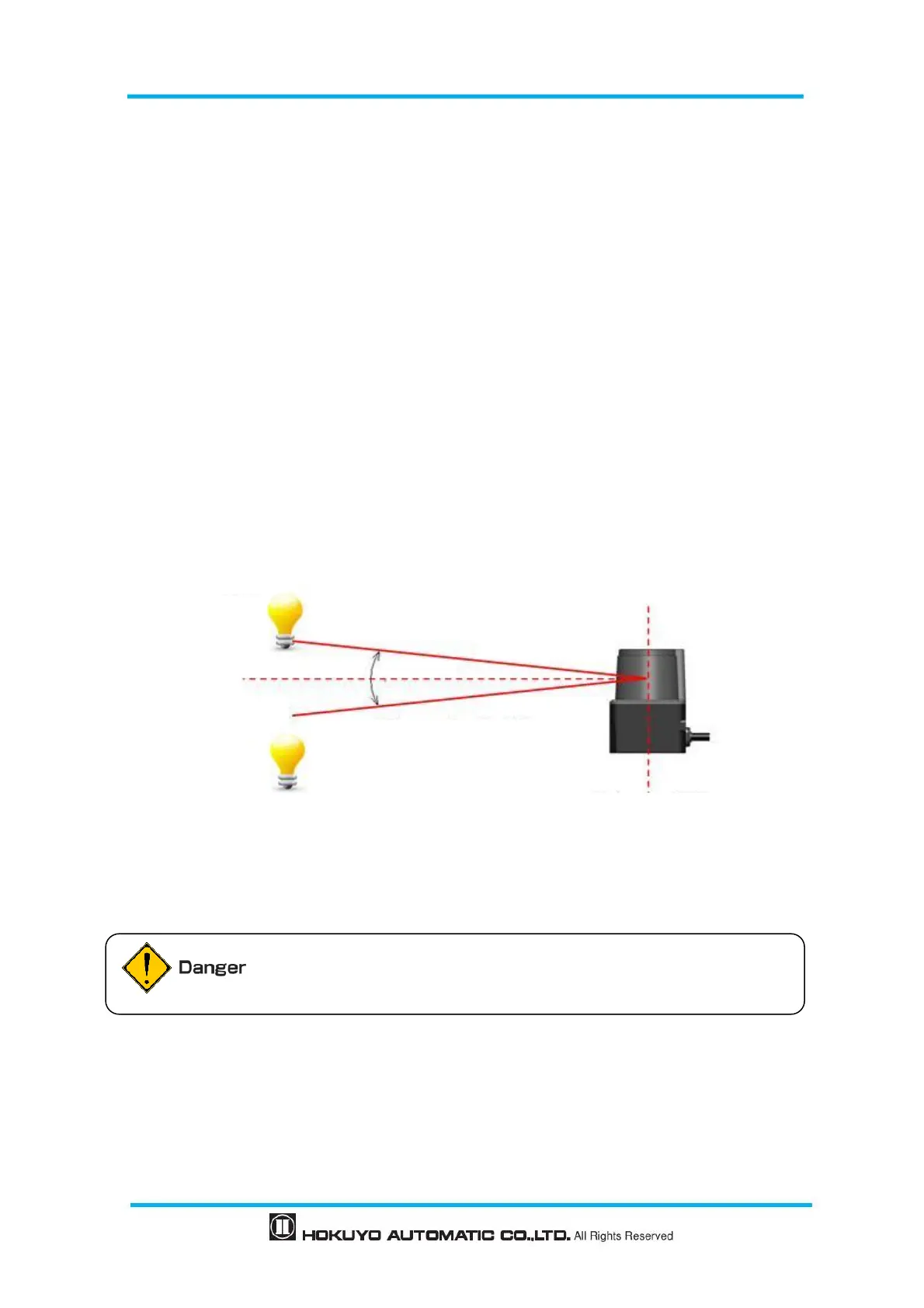
5.1 Light interference
The UST uses a pulsed laser for object detection. Light interference sources could lead to false detection.
User should examine the surrounding environments before installation the sensor.
If the light source cannot be avoided during operation, the UST should be installed with the light source
located at ±5 degrees or more from the detection plane in order to prevent interference as shown in figure
5.1.
Figure 5-1 Installation under light interference
Detection plane with ±5°or more
User must perform risk assessment for interference lights in the working
environment before installation.