Document No: C-41-02490-9
48
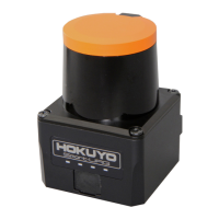
Blue LED: ON during normal operation, blink during the start up,
configuration and malfunction state
Orange LED 1: Output 1 ON during object detection
Orange LED 2: Output 2 ON during object detection
Orange LED 3: Output 3 ON during object detection
Synchronization Master/Slave operation mode (can set by using Area
Designer)
*4
Synchronization slave mode (0°)
Synchronization slave mode (90°)
Synchronization slave mode (180°)
Synchronization slave mode (270°)
Less than 15,000 lx
Note : Avoid direct sunlight or other illumination sources as it may cause
sensor malfunction
Ambient temperature,
humidity
-10°C to +50°C below 85%RH (without dew, frost)
Storage temperature,
humidity
-30°C to +70°C below 85%RH (without dew, frost)
10 to 55Hz double amplitude of 1.5mm for 2hrs in each X, Y, and Z direction
55 to 200Hz 98m / s
2
sweep of 2min for 1hr in each X,Y and Z direction
196m/s
2
(20G) X,Y and Z directions each 10 times
Can record distance, level data, etc., of each step
5 years under normal temperature (motor life)
Optical window : Polycarbonate
Body : Aluminum
50×50×70(mm) (Sensor only)
*1
In the case installing the sensor parallel to the Emitter/Receiver surface. Minimum detectable size of the object
can be set by Area Designer.
*2
Under the factory standard testing condition using white Kent sheet.
*3
Initial setting is 66msec. ON/OFF delay function switching is possible by Area Designer. Response time can be
further delayed by a maximum of 1scan during the area switching.
*4
Initial setting is synchronization master. When using synchronization operation, refer to section 5.3 for details
about synchronization wiring. Synchronization slave setting is possible using Area Designer.
*5
The recorded distance data, level data, etc., can be confirmed using Area Designer application.
For detail refer to Area Designer UST series sensor configuration instruction manual.