16-1
16. IGNITION SYSTEM
SERVICE INFORMATION
GENERAL
• Some electrical components may be damaged if terminals or connectors are connected or disconnected while the ignition
switch is ON and current is present.
• When servicing the ignition system, always follow the steps in the troubleshooting on page 16-2.
• The CDI ignition system uses an electrically controlled ignition timing system. No adjustments can be made to the ignition
timing.
• The ignition control module (ICM) may be damaged if dropped. Also, if the connector is disconnected when current is flowing,
the excessive voltage may damage the ICM. Always turn off the ignition switch before servicing.
• A faulty ignition system is often related to poor connections. Check those connections before proceeding.
• Make sure the battery is adequately charged. A weak battery may be unable to turn the starter motor quickly enough, or
adequate ignition current may not be supplied.
• Use spark plug of the correct heat range. Using spark plug with an incorrect heat range can damage the engine.
• For ignition switch inspection, see section 18.
• For ignition pulse generator (alternator starter) removal/installation, see section 10.
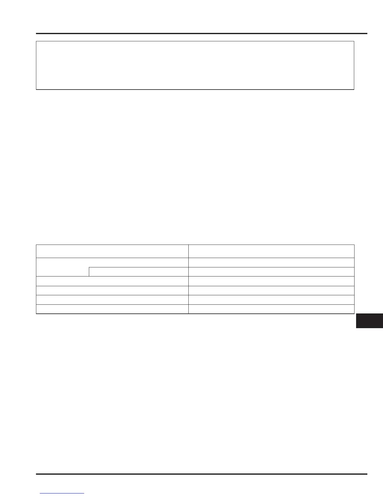
SPECIFICATIONS
SYSTEM DIAGRAM 16-0
SERVICE INFORMATION 16-1
TROUBLESHOOTING 16-2
IGNITION SYSTEM INSPECTION 16-3
IGNITION TIMING 16-6
IGNITION COIL 16-6
IGNITION CONTROL MODULE (ICM) 16-6
THROTTLE SWITCH 16-7
16
SPECIFICATIONS
Ignition primary peak voltage
Exciter coil peak voltage
Ignition pulse generator peak voltage
Ignition timing (“F” mark)
NGK CPR7EA-9
CPR7EA-9
100 V minimum
100 V minimum
0.7 V minimum
15° BTDC at idle speed
ITEM
Standard
Spark plug
TOOLS
Imrie diagnostic tester (model 625) or
Peak voltage adaptor 070GJ – 002I110 with
Commercially available digital multitester (impedance 10 MΩ/DCV minimum)

 Loading...