18-9
LIGHTS/METERS/SWITCHES
G
Y/W
Bl
FUEL UNIT 2P
CONNECTOR
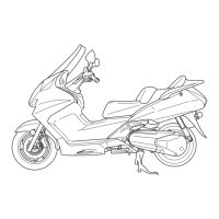
BRAKE LIGHT SWITCH
Remove the front handlebar cover (page 2-7).
Disconnect the brake light switch connector and check
for continuity between the switch terminals.
There should be continuity with the brake lever applied,
and there should be no continuity with the brake lever is
released.
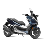
FUEL METER/FUEL UNIT
INSPECTION
Lift up the body cover (page 2-3).
Disconnect the fuel unit 2P connector.
Short the Yellow/White and Green wire terminals of the
fuel level sensor 2P connector with the suitable jumper
wire.
Turn the ignition switch ON and check the fuel meter
needle. The needle should move to “F”.
If the needle does not move, check the following.
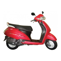
Remove the combination meter (page 18-5).
Connect the combination meter 6P connector and black
wire connector.
Check for open circuit in yellow/white between the meter
and fuel level sensor.
If yellow/white wire is OK, measure the voltage between
the black wire (+) and green wire (–) with the ignition
switch ON.
There should be battery voltage.
If there is no voltage, check for open circuit in black wire
and/or green wire.
If the needle moves, check the fuel level sensor.
Install the removal parts in the reverse order of removal.
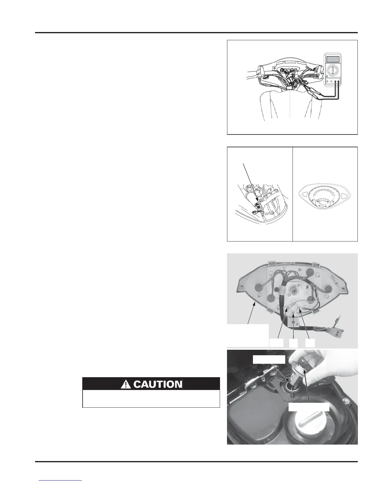
FUEL UNIT REMOVAL
Connect the fuel unit 2P connector.
Remove the fuel unit cover.
Turn the fuel unit holder plate counterclockwise with a
pair of needle nose pliers and remove the fuel unit and
unit holder plate.
COMBINATION
METER
FUEL UNIT
UNIT HOLDER
• Be careful not to damage the unit cable.
• Be careful not to bend the float arm of the unit.
 Loading...