BF15D-BF20D
4)
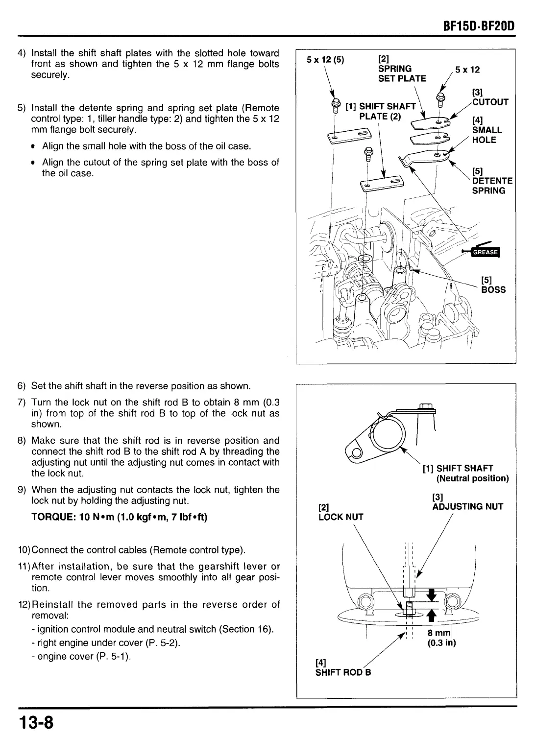
Install the shift shaft plates with the slotted hole toward
front as shown and tighten the
5
x
12 mm flange bolts
securely.
5)
Install the detente spring and spring set plate (Remote
control type: 1, tiller handle type: 2) and tighten the
5
x
12
mm flange bolt securely.
Align the small hole with the boss of the oil case.
Align the cutout of the spring set plate with the
boss
of
the oil case.
6)
Set the shift shaft in the reverse position as shown.
7)
Turn the lock nut on the shift rod
B
to
obtain
8
mm
(0.3
in) from top of the shift rod
B
to
top of the lock nut as
shown.
8)
Make sure that the shift rod is in reverse position and
connect the shift rod
B
to the shift rod A by threading the
adjusting nut until the adjusting nut comes in contact with
the lock nut.
9)
When the adjusting nut contacts the lock nut, tighten the
lock nut by holding the adjusting nut.
TORQUE:
10
Nom
(1.0
kgfom,
7
Ibfoft)
10)Connect the control cables (Remote control type).
11)After installation, be sure that the gearshift lever
or
remote control lever moves smoothly into all gear posi-
tion.
12)Reinstall the removed parts in the reverse order of
removal:
-
ignition control module and neutral switch (Section 16).
-
right engine under cover
(P.
5-2).
-
engine cover
(P.
5-1).
5
x
12
(5)
121
SPRING
\
SET PLATE
/
l2
b
[I]
SHIFT SHAFT
131
[41
,CUTOUT
SMALL
HOLE
151
DETENTE
SPRING
rii
SHIFT
'
SHAFT
PI
LOCK NUT
_-
(Neutral position)
131
ADJUSTING NUT
/
13-8