AQ251 SERIES BOILER RESET CONTROL PANELS
37 69-1974—04
TEST ZONES Tests the zone equipment individually, or sequentially, to ensure correct operation
ALL ZONES n/a OFF Sequentially energizes / de-energizes all zones connected
to the AQUATROL network.
• 0 displays when the Control Module has confirmation
that the pump/valve is closed.
• 1 displays when the Control Module has confirmation
that the pump/valve is fully open.
In the case of pump zoning, the 1 displays no more than 5
seconds after the activation of the relay. In the case of valve
zoning, the 1 displays either when the zone valve operating
time (defined in EQUIPMENT SETUP > ZONING > ZONE
VALVES TIME TO OPEN) has elapsed (AQ15540B) or
when the valve’s end switch is closed (AQ15740B).
ZONE A-1 0
…
ZONE A-16 0
0 / 1 0 Energizes / de-energizes each zone individually.
• 0 displays when the Control Module has confirmation
that the pump/valve is closed.
• 1 displays when the Control Module has confirmation
that the pump/valve is fully open.
PURGE Purges all (or individual) zones for the period of time selected in the PURGE TIME menu option
PURGE TIME 1 to 30
(minutes)
5:00
(minutes)
Duration of purge for each zone selected.
PURGE ALL / DHW /
ZONE A-1 … ZONE D-16
ALL Installer selects which zones to purge (all, only DHW, or
individual zones).
START PURGE START PURGE /
STOP PURGE
n/a Starts and Stops purge operation.
PURGE OFF WAIT VALVE /
PURGE COMPLETED
n/a Indicates status of the system during a Purge operation.
Displays only if START PURGE is active.
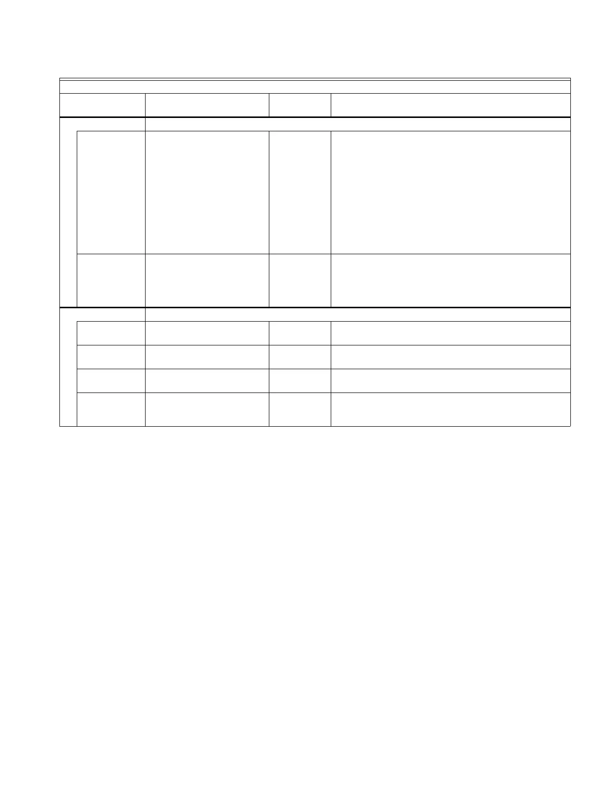
Table 7. Installer Menu – Test and Purge. (Continued)
TEST and PURGE
Menu Option Range
Factory
Default Description

 Loading...


