AQ251 SERIES BOILER RESET CONTROL PANELS
69-1974—04 6
3 WIRING PROCEDURE
The AQ251 Control Panel is pre-wired at the factory, making
for faster installation:
• For all models, the low voltage output terminals located at
the top of the transformer are wired to the R and C input
terminals of the Control Module.
• For those Control Panel models that come with Zoning
Modules included, (all but the AQ25110B), the transformer’s
low voltage outputs are also wired to the R and C inputs of
the Zoning Module. The B-B “Exp. Bus” terminals of the
Control Module are wired to the B-B “Exp. Bus IN” terminals
of the Zoning Module.
Beginning with the top left of Fig. 4 and moving clockwise
around the panel, wire components to the AQ251 Control
Panel and Expansion Zoning Panels (if installed) in the
following six steps:
• “Step 1 – Transformer Wiring”
• “Step 2 – Control Panel Wiring”
• “Step 3 – Thermostats Wiring” on page 9
• “Step 4 – Zoning Equipment Wiring” on page 9
• “Step 5 – Line Voltage System Outputs” on page 12
• “Step 6 – Connection to Line Voltage Power” on page 13
Fig. 4. Wiring sequence.
Step 1 – Transformer Wiring
Factory pre-wiring of the Control Panels is shown as dotted
lines in Fig. 4.
In addition to the pre-wiring, run low voltage jumper wires from
available R and C terminals on the secondary of the
transformer to the R and C terminals of any Expansion Zoning
Panel.
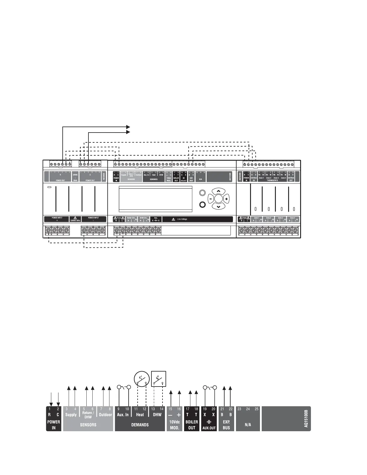
Step 2 – Control Panel Wiring
Wire the Temperature Sensors, System Demands, Low
Voltage Outputs, and Communication Bus (Refer to Fig. 5 for
wiring terminals on the top of the AQ251):
• “Temperature Sensor Wiring” on page 7
• “System Demands Wiring” on page 7
• “Low Voltage Outputs Wiring” on page 8
• “Communication Bus Wiring” on page 8
Fig. 5. Low voltage wiring for the AQ15100B Control Module.
M27738
Menu
Home
OK
Zone 1
Zone 2 Zone 3
Zone 4
STEP 1 STEP 2 STEP 3
STEP 4STEP 5STEP 6
TO EXPANSION ZONING MODULES
(IF INSTALLED)
TO BOILER SUPPLY SENSOR
TO BOILER RETURN SENSOR
TO OUTDOOR SENSOR
IN FROM “R” TERMINAL ON
TRANSFORMER MODULE
(FACTORY-WIRED)
TO “T-T” TERMINALS ON
BOILER AQUASTAT
TO B-B “EXP.BUS IN”
TERMINALS ON CONNECTED
ZONING MODULE
TO SETPOINT LOAD
(OPTIONAL)
TO DHW AQUASTAT
IN FROM “C” TERMINAL
ON TRANSFORMER MODULE
(FACTORY-WIRED)
M27739A
TO LOW VOLTAGE AUXILIARY
DEVICE (OPTIONAL)
TO AUXILIARY INPUT
SWITCH (OPTIONAL)
TO MODULATING INPUT
ON BOILER

 Loading...


