AQ251 SERIES BOILER RESET CONTROL PANELS
5 69-1974—04
2MOUNTING
This section describes how to mount the Control Panel,
Expansion Zoning Panels, and the Thermostats.
Mount AQ251 Control Panel
Mount the control panel on the wall:
1. Use the template supplied with the AQ251 Series
Control Panel to mark mounting holes for panels
2. Install two top screws, mount the panel, and install the
two lower screws.
Mount Expansion Zoning Panel(s)
If there are Expansion Zoning Panels to install, mount them to
the wall now:
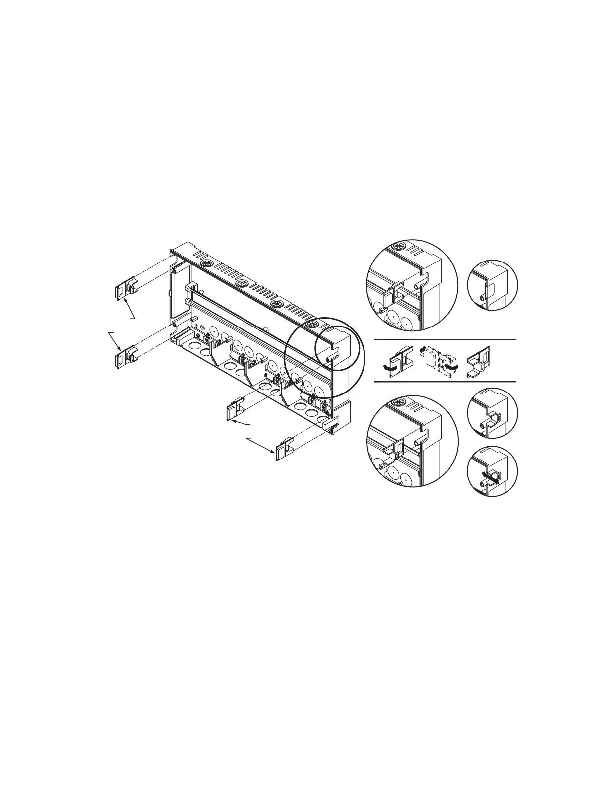
1. Remove wire channel plugs from the AQ251 Control
Panel and any Expansion Zoning Panels (see Fig. 3).
2. Mount Expansion Zoning Panel on the right-hand end of
the AQ251 Control Panel. Install two top screws of the
Expansion Zoning Panel, ensuring it is level with the
adjoining Control Panel, and install two lower screws.
3. Reverse wire channel plugs and re-insert them into their
slot, to form a wiring channel between the Control Panel
and the Expansion Zoning Panel (see Fig. 3) and to
connect the two panels together.
4. Repeat steps 1–3 for any additional Expansion Zoning
Panels.
Fig. 3. Orientation of wire channel plugs for creating pass-through wire channel and
for joining Control Panel to Expansion Zoning Panels.
Mount and Wire Thermostats in the Zones
Install the thermostats on the walls in the zones that are to be
controlled by the AQ251 Control Panel.
When using AQ1000 thermostats refer to the installation
instructions (form #69-2005) included with the AQ1000
thermostats.
If not done already, run low voltage thermostat wire (24 gauge
or heavier) from the thermostats back to the Zoning Modules
connected to the AQ251 Control Panel.
NOTES: If not otherwise specified, low voltage wiring should
be run with 18 gauge thermostat wire and line voltage
wiring should be run with 14 gauge wire.
AQUATROL® line voltage screw terminals are only
approved for use with 22 to 12 gauge copper
conductors.
Several wiring diagrams are included in this
document. For additional information, refer to
http:// customer.honeywell.com or your local
distributor.
M23733A
WIRE
CHANNEL
PLUGS
WIRE
CHANNEL
PLUGS

 Loading...


