AQ251 SERIES BOILER RESET CONTROL PANELS
13 69-1974—04
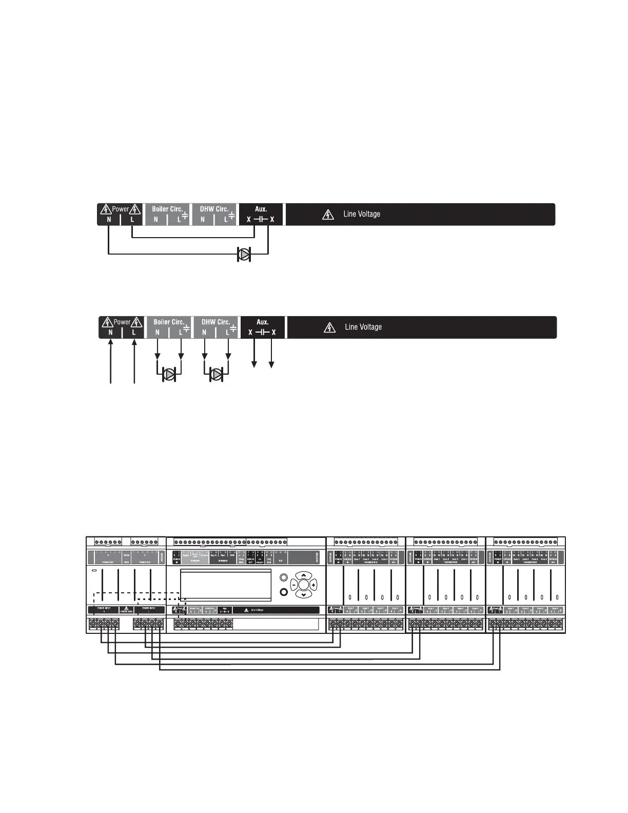
3. Line Voltage Rated Aux Output (Aux. pump)
To connect a line voltage auxiliary device to these contacts,
such as a boiler bypass pump, power the pump from the N and
L terminals on the bottom of the Control Module, running the L
(hot) lead through the AUX.Pump contacts. See Fig. 16 for
details. The exact wiring schematic will depend on what is
connected to these dry contacts.
The Aux Pump is a line voltage-rated dry contact that is
controlled by the selection in the EQUIPMENT SETUP >
AUXILIARY I/O sub-menu (see Fig. 25 on page 39).
NOTE: Use of this output is optional. The Aux. pump dry
contacts are line voltage-rated but unpowered. A low
voltage device can be connected to these
programmable contacts, but the wire's insulation must
meet applicable codes for use in line voltage
enclosures.
See page 30 for programming options for the Aux.
Pump dry contacts.
Fig. 16. Wiring of the Aux. pump line voltage rated dry contacts (example shown is a by-pass pump).
Fig. 17. Wiring for Boiler Pump, DHW Device, and Aux Output.
Step 6 – Connection to Line Voltage Power
Connect the N and L line voltage inputs of the AQ251 Control
Panel (at the bottom of the transformer) to the electrical
distribution panel and power up the Control. A service switch
should be installed on the hot (L) lead to the distribution panel.
If multiple Zoning Modules are connected to the AQ251
Control Panel, the line voltage wiring can either be run directly
from the N and L terminals on the primary of the transformer to
each Zoning Module (Fig. 18), or run in a daisy chain from the
N and L terminals of one AQ2000 module to the N and L
terminals of the next AQ2000 module (Fig. 19 on page 14).
Fig. 18. Connections for multiple Zoning Panels - parallel wiring.
BY-PASS PUMP
M27743A
TO AUXILIARY DEVICE
(INSTALLER-DEFINED)
FROM LINE VOLTAGE
120V TERMINALS
(N AND L) ON BOTTOM
OF TRANSFORMER
M27744A
Zone 1
Zone 2
Zone 3
Zone 4
Zone 1
Zone 2
Zone 3
Zone 4
Zone 1
Zone 2 Zone 3
Zone 4
M27745A
Menu
Home
OK

 Loading...


