AQ252 Universal Injection/Mixing Boiler Reset Control Panels
11 69-1986—02
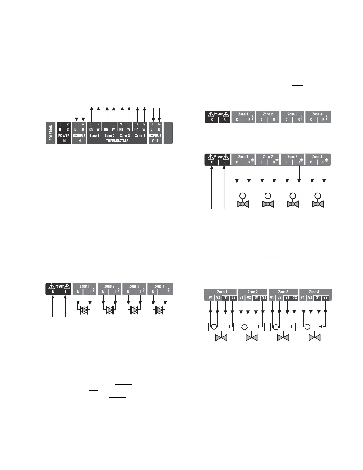
Fig. 9. Connecting thermostats.
Step 4 – Zoning Equipment Wiring
Because the Zoning Module of the AQ25242B Control Panel
can be used with either line voltage pumps or valves, or low
voltage zone valves (with or without end switches), field
installed wiring of the correct voltage needs to be connected to
the zoning equipment terminals on the bottom left portion of
the Zoning Module.
Line Voltage – Circulators or Zone Valves
Refer to Fig. 10. Remove the plastic wiring barrier that is
located in the bottom wiring channel between the AQ15200B
Control Module and the Zoning Module. Run jumper wires from
the N and L terminals on the bottom of the AQ252 Control
Panel’s transformer, through the wiring channel across the
bottom of the Control Panel, and to the corresponding N and L
terminals of the Zoning Module.
Fig. 10. Wiring an AQ15540B Zoning Module for use
with line voltage circulators.
Low Voltage – Zone Valves With or Without End
Switches
Wire using step 1 for zone valves without end switches, or use
step 2 for zone valves with
end switches:
1. Low voltage zone valves without
end switches:
Using Fig. 12 on page 11 as a guide, run jumper wires
from the R and C terminals on the secondary of the
AQ252’s transformer, through the wiring channel across
the top of the Control Panel, and down through the wiring
channel on the right side of the panel and over to the R
and C terminals on the bottom of the Zoning Module.
IMPORTANT
If low voltage zone valves are used with the
AQ25242B Control Panel, the supplied Low Voltage
Output sticker (shown in Fig. 11) must
be applied over
the line voltage output sticker (see Fig. 10) that is
already attached to the Zoning Module.
Fig. 11. Low voltage output sticker.
Fig. 12. Wiring an AQ15540B Zoning Module for use
with low voltage zone valves without
end switches.
2. Low voltage zone valves with end switches:
See Fig. 13. 24 Vac power is pre-wired between the
transformer secondary at the top left of the AQ252’s
transformer and the AQ15740B Zoning Module. No field
wiring is required.
Fig. 13. Wiring an AQ15740B Zoning Module for use
with low voltage zone valves with
end switches.
NOTE: When wiring zone valves with end switches, note the
transformer's VA:
If low voltage zone valves with end switches are used
for zone control, make sure the selected zone valves
do not draw more power (VA) than the 38 VA capacity
of the AQ10X38 transformer supplied with the AQ252
Control Panel. This integral transformer has enough
power to operate 4 motorized zone valves (such as
Honeywell V8043E valves or 4 valves using low-
amperage draw, heat motor actuators, such as
Honeywell MV100 actuators), plus power the
electronics of the AQ252's Control Module and up to
FROM B-B “EXP. BUS”
TERMINALS ON
CONTROL MODULE
TO B-B “EXP. BUS IN” TERMINALS
ON CONNECTED ZONING MODULE
(IF AN EXPANSION ZONING PANEL
IS CONNECTED)
THERMOSTAT ON ZONE 1
THERMOSTAT ON ZONE 2
THERMOSTAT ON ZONE 3
THERMOSTAT ON ZONE 4
M13776C
FROM LINE VOLTAGE
120V TERMINALS
(N AND L) ON BOTTOM
OF TRANSFORMER
M27687
M27688A
FROM LOW VOLTAGE
24 VAC TERMINALS
(C AND R) ON TOP
OF TRANSFORMER
M M M M
M27689A
M
M27690A
M
M
M

 Loading...


