AQ25400B “ADD-A-TEMPERATURE” EXPANSION CONTROL PANEL
69-1987—02 4
modulating signal to drive a modulating mixing valve or a
variable speed pump, and a 24 Vac set of terminals that
provides a floating signal to a motorized mixing valve.
Line voltage outputs include a secondary pump relay and a
variable speed injection output which drives a fixed speed
circulating pump at a varying speed depending on the heat
input required for the secondary mixed loop.
On the bottom of the Control Module, there is a set of line
voltage-rated auxiliary (AUX.) dry contacts that can be
programmed to close under several predefined conditions,
making this Control Panel a very versatile mixing controller for
hydronic systems.
MOUNTING
Since the AQ254 “Add-A-Temperature” Panel is an Expansion
Control Panel, it functions as an “add-on” control to an existing
Main AQ2000 Series Boiler Control. The AQ254 is designed to
be connected to an AQ2000 boiler Control Panel - it cannot be
operated as a standalone device.
IMPORTANT
The Main AQ2000 Series Control Panel (an AQ250,
AQ25A, AQ251, or AQ252), and any Expansion Zon-
ing Panels connected to the Main panel) must be
mounted on the wall of the mechanical room before
the AQ254 can be installed.
Mount AQ254 Control Panel
Mount the control panel on the wall using Fig. 2 as a guide:
1. Remove the wire channel plugs from the AQ254.
2. Mount the AQ254 on the right hand end of the main
AQ2000 Series Control Panel (or Expansion Zoning
Panel).
3. Reverse the wire channel plugs and re-insert them into
the groove from where they were removed to form a wir-
ing channel between the main AQ2000 Series Control
Panel (or Expansion Zoning Panel) and the “Add-A-Tem-
perature” Control Panel.
4. Install the two top screws, mount the panel, and install
the two lower screws.
Mount Expansion Zoning Panel(s)
If there are Expansion Zoning Panels to install, mount them to
the wall now:
1. Remove wire channel plugs from the AQ254 Control
Panel and any Expansion Zoning Panels (see Fig. 2).
2. Mount Expansion Zoning Panel on the right-hand end of
the AQ254 Control Panel. Install two top screws of the
Expansion Zoning Panel, ensuring it is level with the
adjoining Control Panel, and install two lower screws.
3. Reverse wire channel plugs and re-insert them into their
slot, to form a wiring channel between the Control Panel
and the Expansion Zoning Panel. Refer to Figure
Fig. 5 on page 7 for an example of an installation with
multiple AQ254 Expansion Control Panels
4. Repeat steps 1–3 for any additional Expansion Zoning
Panels.
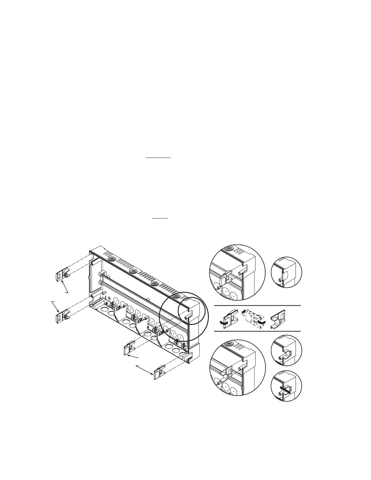
Fig. 2. Orientation of wire channel plugs for creating pass-through wire channel and
for joining Control Panel to Expansion Zoning Panels.
M23733A
WIRE
CHANNEL
PLUGS
WIRE
CHANNEL
PLUGS

 Loading...


