AQ25400B “ADD-A-TEMPERATURE” EXPANSION CONTROL PANEL
17 69-1987—02
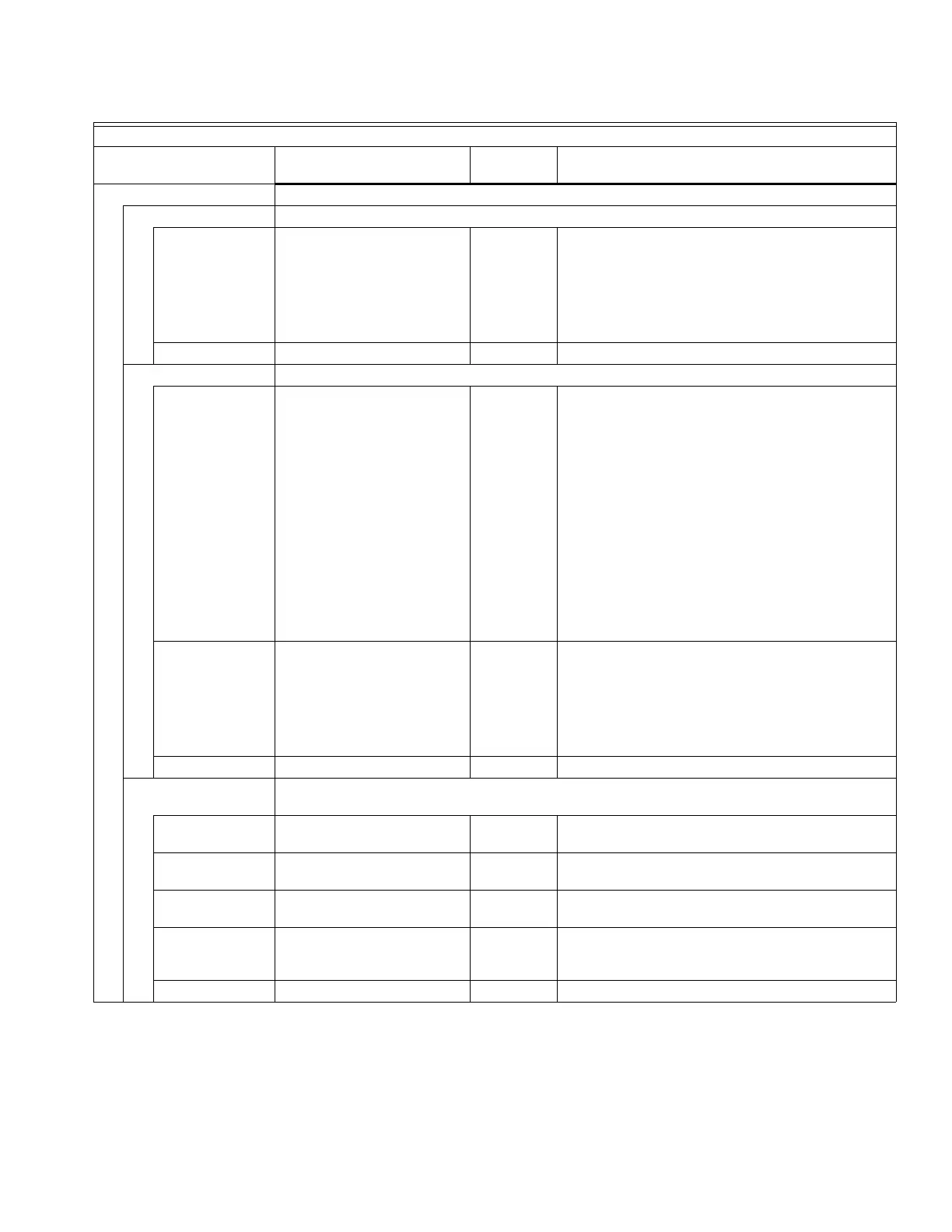
TEST (continued)
SENSOR Tests the secondary mixed loop temperature sensor to ensure correct operation
SEC - -
LO
-49° to 257°F (-45° to 125°C)
HI
n/a Displays the temperature measured by the secondary
mixed water sensor.
• “- -” means sensor is disconnected
• LO means temperature reading is below -49°F (-
45°C)
• HI means temperature reading is above 257°F
(125°C)
EXIT n/a n/a Exits this sub-menu and returns to the Installer menu.
ZONES Tests the zone equipment individually, or sequentially, to ensure correct operation
ALL n/a OFF Sequentially energizes / de-energizes all zones
connected to the AQ254 group of zones.
• 0 displays when the AQ254 Control Module has
confirmation that the zone’s pump is de-energized
or its valve is fully closed.
• 1 displays when the AQ254 Control Module has
confirmation that the zone’s pump is energized or
its valve is fully open.
In the case of pump zoning, the 1 displays no more
than 5 seconds after the activation of the relay. In the
case of valve zoning, the 1 displays either when the
zone valve operating time (defined in EQUIPMENT
SETUP > ZONING > ZONE VALVES TIME TO OPEN
on the main AQ2000 Series Control Panel) has
elapsed (AQ1554P2) or when the valve’s end switch
is closed (AQ1574V4).
ZONE B-1 0/1
…
ZONE B-16 0/1
0/1 0 Energizes / de-energizes each zone individually.
• 0 displays when the AQ254 Control Module has
confirmation that the zone’s pump is de-energized
or its valve is fully closed.
• 1 displays when the AQ254 Control Module has
confirmation that the zone’s pump is energized or
its valve is fully open.
EXIT n/a n/a Exits this sub-menu and returns to the Installer menu.
PURGE Purges all (or individual) zones for the period of time selected in the PURGE TIME menu
option
PURGE TIME 1 to 30
(minutes)
5:00
(minutes)
Duration of purge for each zone selected.
PURGE PURG ALL / DHW /
PURGE 1 … PURGE 16
ALL Installer selects which zones to purge (all, only DHW,
or individual zones).
START PURGE START PURGE /
STOP PURGE
n/a Starts and Stops purge operation.
PURGE OFF WAIT VALVE /
PURGE COMPLETE
n/a Indicates status of the system during a Purge
operation.
Displays only if START PURGE is active.
EXIT n/a n/a Exits this sub-menu and returns to the Installer menu.
Table 3. Installer Menu. (Continued)
EQUIPMENT SETUP
Menu Option Range
Factory
Default Description

 Loading...


