Honeywell | 31
8 Configuring CloudLink 5G Modem
8 Configuring CloudLink 5G Modem
This chapter describes the configuration of a CloudLink 5G Modem device using the MasterLink
desktop application.
MasterLink desktop application is a configuration and diagnostic software designed for Electronic
Volume Corrector EC350 and CloudLink 5G Modem. The primary purpose is to configure, calibrate,
deploy, and download data from EC350 and CloudLink 5G through MasterLink application.
When you connect a CloudLink 5G Modem device to MasterLink, you can configure it as:
a. CloudLink 5G modem, or
b. EC350/ERX350 + CloudLink 5G Modem as an Integrated device.
To learn more about MasterLink, EC350/ERX350, or CloudLink 5G Modem, refer to their respective
user guides available on the Honeywell Process Website.
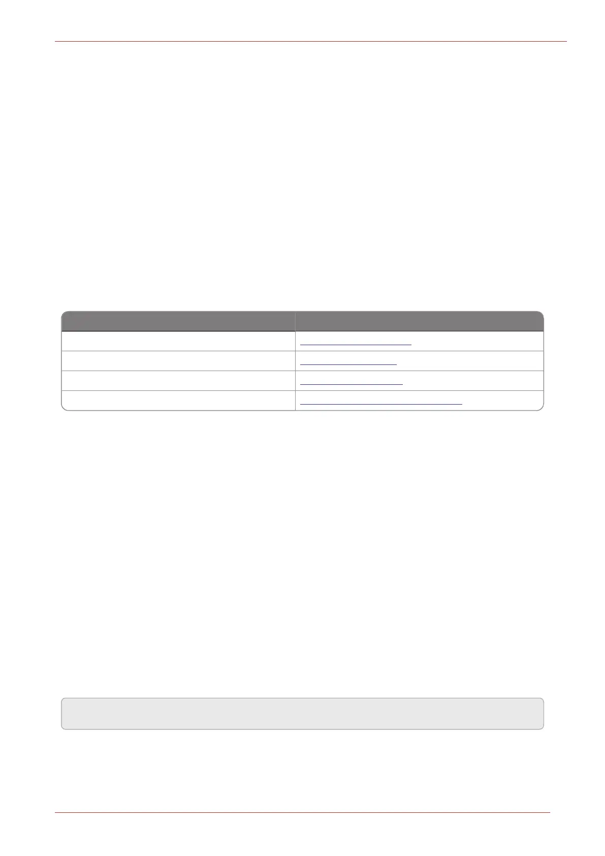
Product Name Documentation Link
Honeywell MasterLink Software MasterLink User Guide
Honeywell EC350 EC350 User's Guide
Honeywell ERX350 ERX350 User's Guide
CloudLink 5G Modem CloudLink 5G Modem User Guide
8.1 Operating Modes
The CloudLink 5G Modem has 2 operating modes:
1. Normal mode: Also known as power saving mode where the modem connects to remote host
based on configured call profile in the integrated instrument/EVC. Else the device sleeps sav-
ing power, recommended for battery powered application (i3142 is disabled).
2. Continuous Server mode: Where the modem is always connected to network and waiting for a
remote host to dial out, recommended for non-battery powered application (i3142 is enabled)
8.2 Deployment Scenarios
The CloudLink 5G Modem can be deployed in the following two ways:
1. Standalone mode: Where the modem functions as an independent device.
2. Integrated mode: Where the modem is connected and used with an instrument/EVC device
connected over board-to-board connector using UART and RS232 serial communication.
Note: The screenshots provided throughout the manual are just for reference.