10 Technical Data
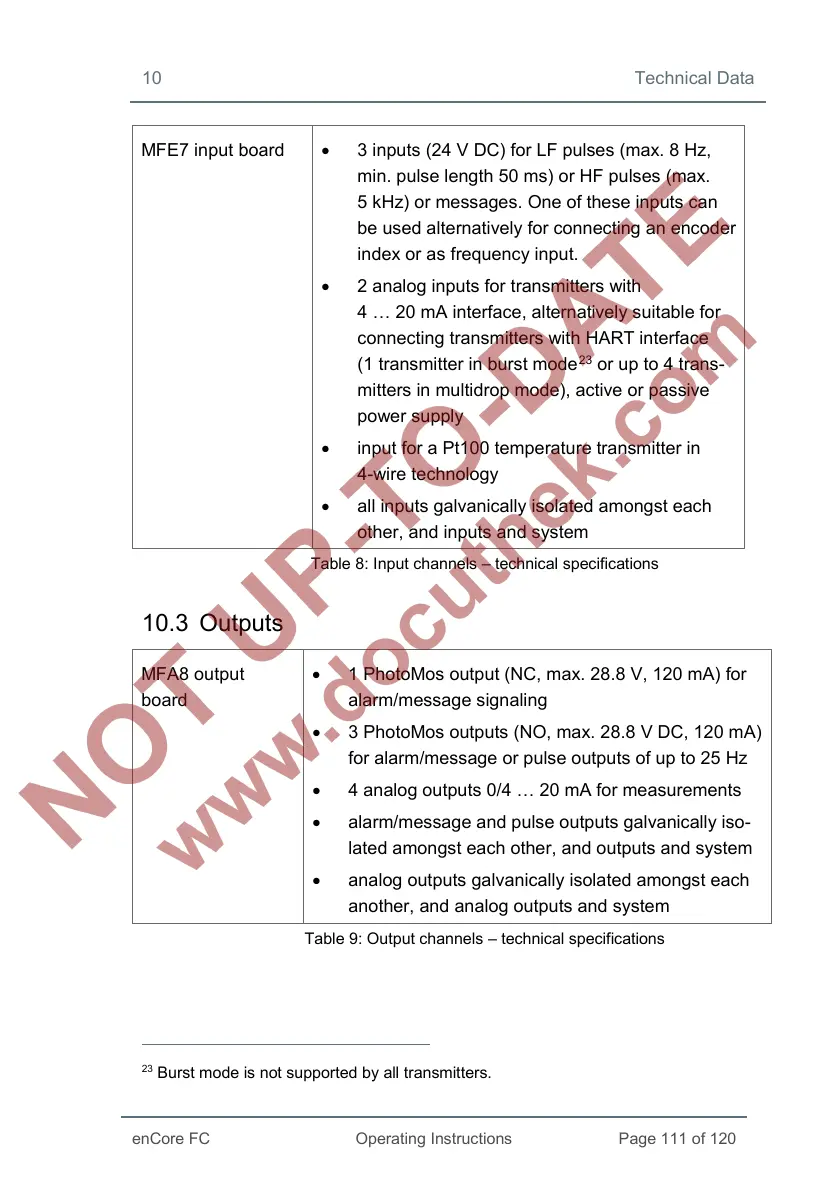
MFE7 input board • 3 inputs (24 V DC) for LF pulses (max. 8 Hz,
min. pulse length 50 ms) or HF pulses (max.
5 kHz) or messages. One of these inputs can
be used alternatively for connecting an encoder
index or as frequency input.
• 2 analog inputs for transmitters with
4 … 20 mA interface, alternatively suitable for
connecting transmitters with HART interface
(1 transmitter in burst mode
23
or up to 4 trans-
mitters in multidrop mode), active or passive
power supply
• input for a Pt100 temperature transmitter in
4-wire technology
• all inputs galvanically isolated amongst each
other, and inputs and system
Table 8: Input channels – technical specifications
10.3 Outputs
MFA8 output
board
• 1 PhotoMos output (NC, max. 28.8 V, 120 mA) for
alarm/message signaling
• 3 PhotoMos outputs (NO, max. 28.8 V DC, 120 mA)
for alarm/message or pulse outputs of up to 25 Hz
• 4 analog outputs 0/4 … 20 mA for measurements
• alarm/message and pulse outputs galvanically iso-
lated amongst each other, and outputs and system
• analog outputs galvanically isolated amongst each
another, and analog outputs and system
Table 9: Output channels – technical specifications
23
Burst mode is not supported by all transmitters.
 Loading...


