Assembly Instructions 6
• max. cable length depending on the operating mode:
− message, LF or encoder: 500 m
− HF (up to 2 kHz): 250 m
− HF (up to 5 kHz): 100 m
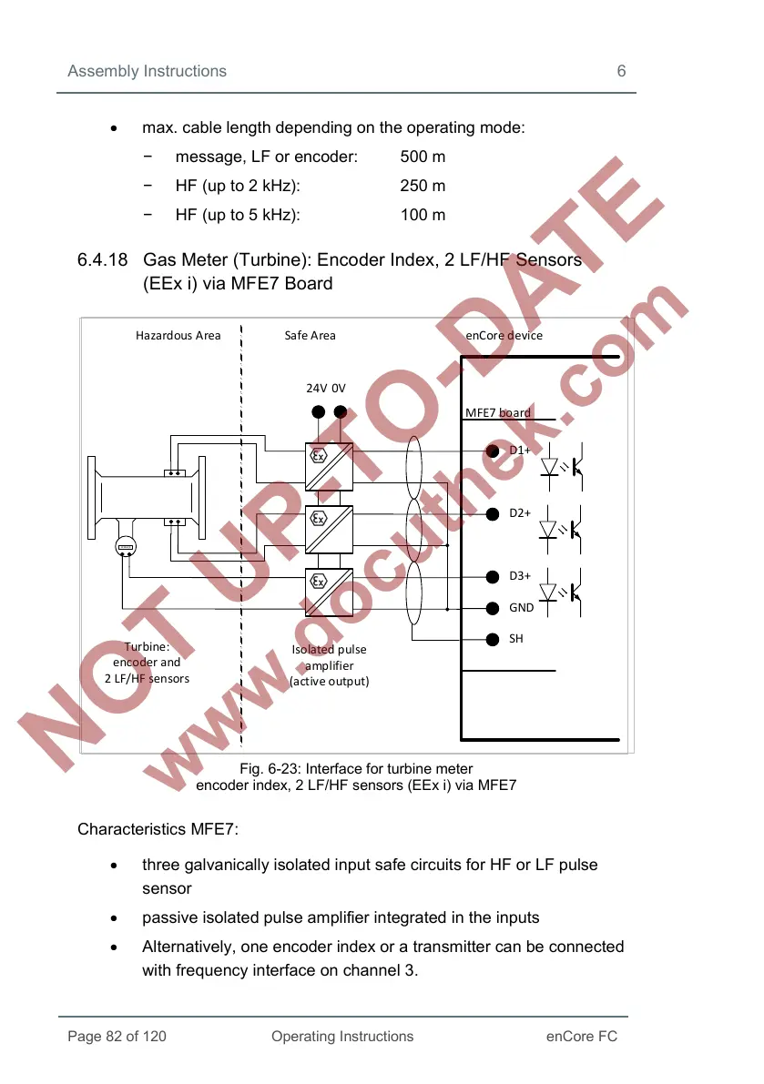
6.4.18 Gas Meter (Turbine): Encoder Index, 2 LF/HF Sensors
(EEx i) via MFE7 Board
Hazardous Area Safe Area enCore device
Turbine:
encoder and
2 LF/HF sensors
24V
0V
Isolated pulse
amplifier
(active output)
MFE7 board
D1+
SH
D2+
D3+
GND
12 345 67 ,8
Fig. 6-23: Interface for turbine meter
encoder index, 2 LF/HF sensors (EEx i) via MFE7
Characteristics MFE7:
• three galvanically isolated input safe circuits for HF or LF pulse
sensor
• passive isolated pulse amplifier integrated in the inputs
• Alternatively, one encoder index or a transmitter can be connected
with frequency interface on channel 3.
 Loading...


