6 Assembly Instructions
• max. cable length: 500 m
Hints on parameterization
Branch <device> – Basic System – I/O boards –
Board <x>: MFE7
Set the following values:
• channel A1+ A1− or A2+ A2−: type Current input
• parameter Power supply: value On (source mode)
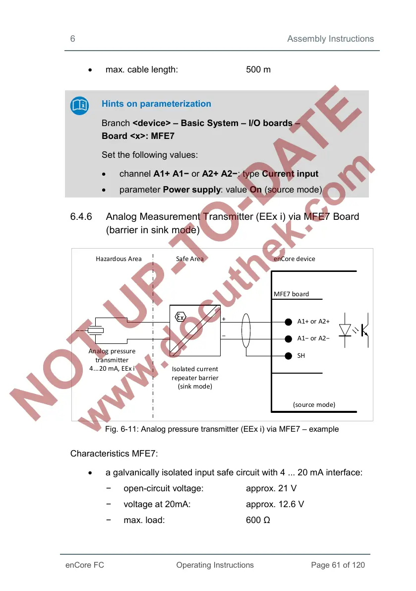
6.4.6 Analog Measurement Transmitter (EEx i) via MFE7 Board
(barrier in sink mode)
Hazardous Area Safe Area
enCore device
MFE7 board
A1+ or A2+
A1− or A2−
SH
Analog pressure
transmitter
4...20 mA, EEx i
Isolated current
repeater barrier
(sink mode)
+
−
(so urce mode)
Fig. 6-11: Analog pressure transmitter (EEx i) via MFE7 – example
Characteristics MFE7:
• a galvanically isolated input safe circuit with 4 ... 20 mA interface:
− open-circuit voltage: approx. 21 V
− voltage at 20mA: approx. 12.6 V
− max. load: 600 Ω
 Loading...


