6 Assembly Instructions
• max. load: 24 V DC
6 mA
• switching point:
− > 15 V DC: (1)
− < 6.5 V DC: (0)
• max. input frequency in operating mode:
− HF: 5 kHz
• max. cable length depending on the operating mode:
− message: 500 m
− HF (up to 2 kHz): 250 m
− HF (up to 5 kHz): 100 m
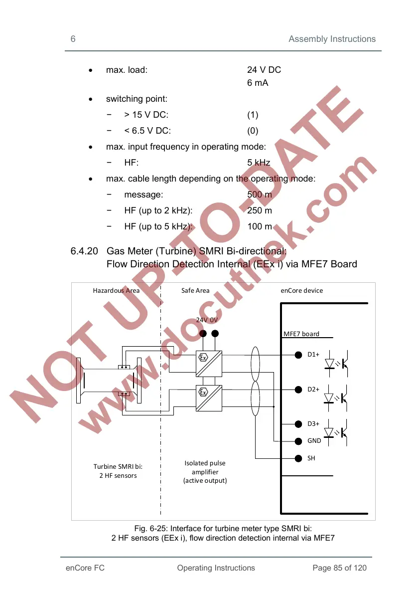
6.4.20 Gas Meter (Turbine) SMRI Bi-directional:
Flow Direction Detection Internal (EEx i) via MFE7 Board
MFE7 board
D1+
SH
D2+
D3+
GND
24V
0V
Hazardous Area Safe Area enCore device
Turbine SMRI bi:
2 HF sensors
Isolated pulse
amplifier
(active output)
Fig. 6-25: Interface for turbine meter type SMRI bi:
2 HF sensors (EEx i), flow direction detection internal via MFE7
 Loading...


