Assembly Instructions 6
Hints on parameterization
Branch <device> – Basic System – I/O boards –
Board <x>: ExMFE5
Set the following value:
• channel P1+ P1−: type Current input
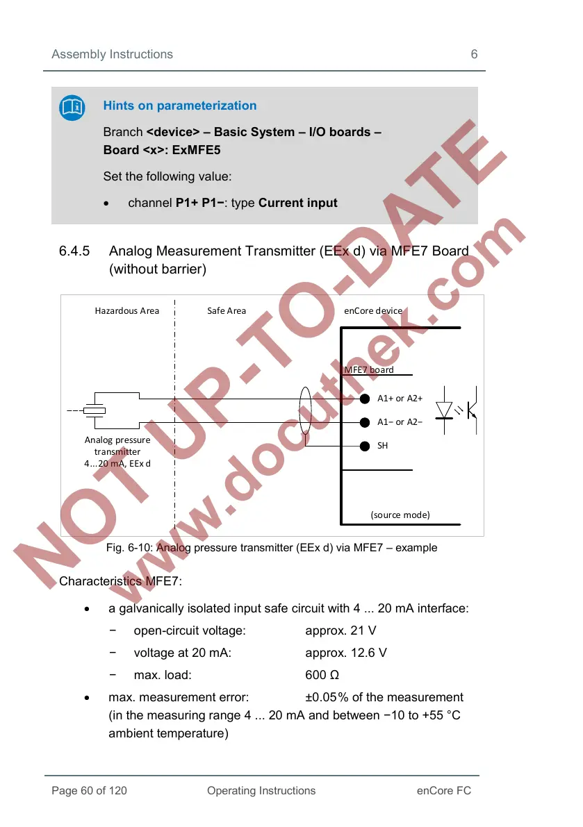
6.4.5 Analog Measurement Transmitter (EEx d) via MFE7 Board
(without barrier)
Hazardous Area Safe Area enCore device
MFE7 board
A1+ or A2+
A1− or A2−
SH
Analog pressure
transmitter
4...20 mA, EEx d
(so urce mode)
Fig. 6-10: Analog pressure transmitter (EEx d) via MFE7 – example
Characteristics MFE7:
• a galvanically isolated input safe circuit with 4 ... 20 mA interface:
− open-circuit voltage: approx. 21 V
− voltage at 20 mA: approx. 12.6 V
− max. load: 600 Ω
• max. measurement error: ±0.05
% of the measurement
(in the measuring range 4 ... 20 mA and between −10 to +55 °C
ambient temperature)
 Loading...


