24 107026-11-EN FR26 ROW 302 Printed in France
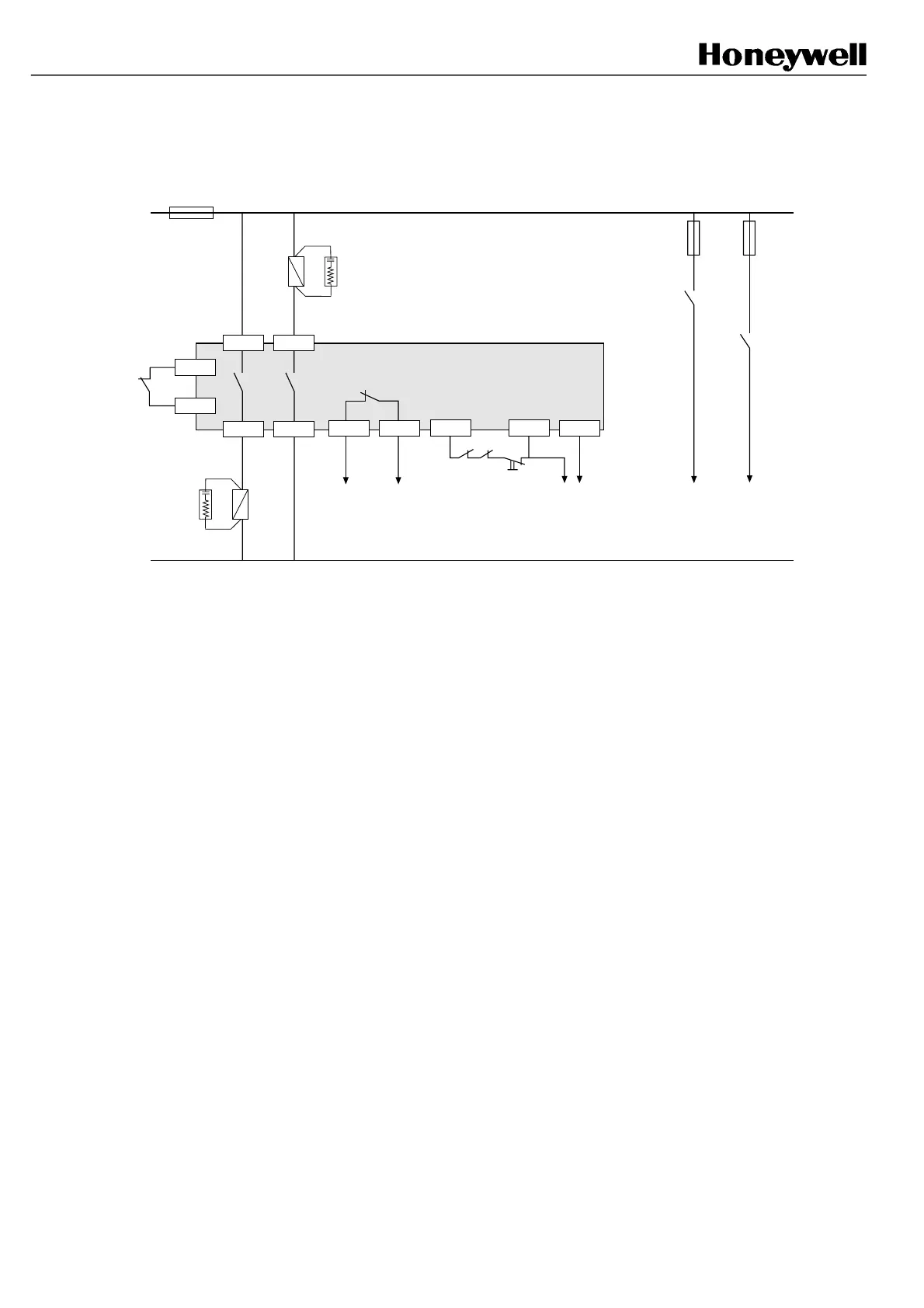
Example 4: Start interlock with Final Switching Device monitoring
(use of example 7 is recommended)
C1 B1
B2C2
C4
B3
Test
K2
Machine stopping
circuitry
FF-SB14R
Signalling
(relay status)
A3
Signalling
(beam status)
C3 C5
K2K1
Start P/B (NC)
A2A1
K2
FSD
K1
FSD
FSD: Final Switching Device * 220 Ω + 0.22 µF
Do not forget to change the jumper links position (refer to § 8.6)
*
*
K1
In this example, it is necessary to press a NC push-button between C3 and C5 to reset the safety barrier at power up
only (automatic reset is performed after any intrusion in the detection field). If the NO contact one of the 2 relays K1
and K2 remains welded, reset is forbidden until the failure is removed. Connecting NC contacts of K1 and K2 in serial
with the NC push-button between terminals C3 and C5 will provide a fault-tolerant connection to the machine stopping
circuitry.
All external relays are safety relays with guided contacts.
FSB14_47
 Loading...