107026-11-EN FR26 ROW 302 Printed in France 23
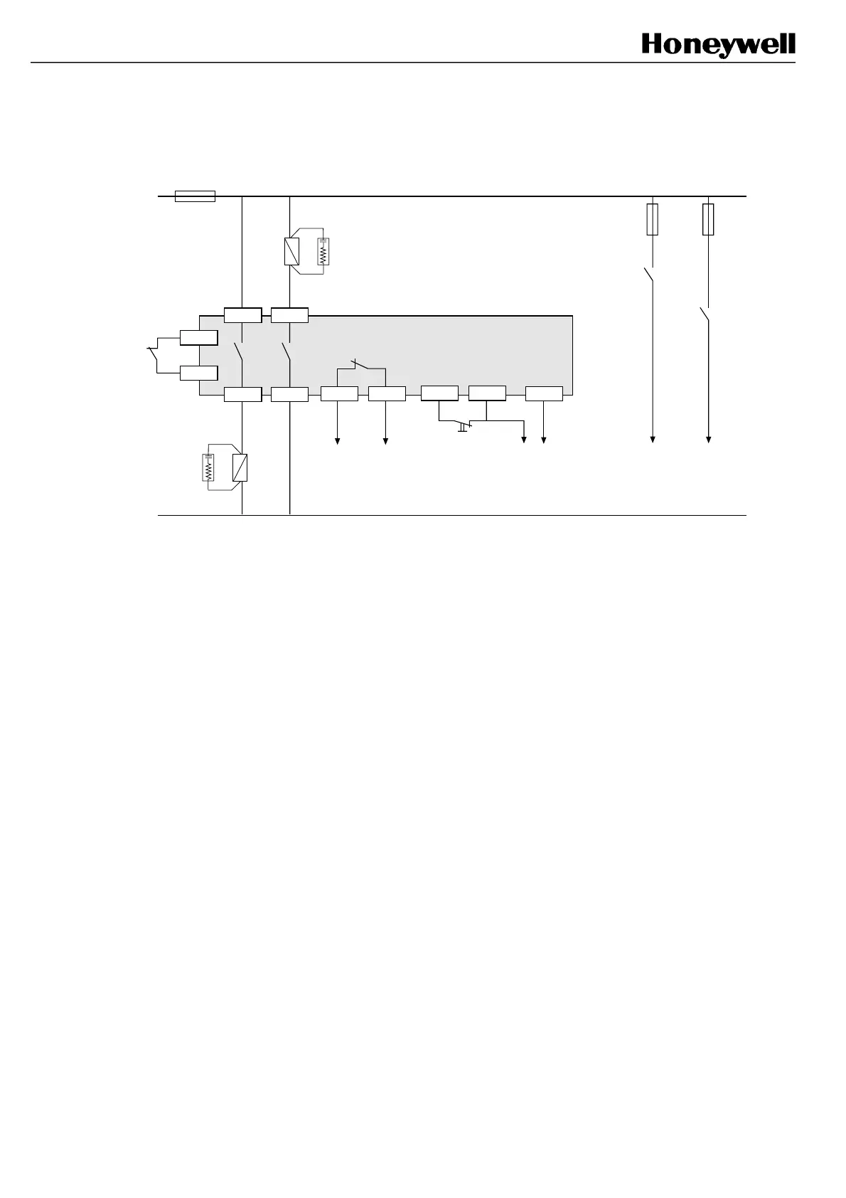
Example 3: Start interlock without Final Switching Device monitoring
(use of example 7 is recommended)
C1 B1
B2
K2
FSD
C2
C4
B3
Test
Machine stopping
circuitry
K1
FSD
FF-SB14R
Signalling
(relay status)
Signalling
(beam status)
C3 C5
Start P/B (NC)
A2A1
K1
K2
FSD: Final Switching Device * 220 Ω + 0.22 µF
Do not forget to change the jumper links position (refer to § 8.6)
*
*
A3
In this example, it is necessary to press a NC push-button between terminal C3 and C5 to reset the safety barrier at
power up only (automatic reset is performed after any intrusion in the detection field). However the additional relays
are not monitored and a possible welded contact on both relays K1 and K2 will not be detected. If a possible failure of
K1 and K2 needs to be detected, please refer to example 4.
FSB14_46
 Loading...