107063-11 EN FR26 GLO 800 Printed in France 23
Check Emission Frequency Setting
Observe the status of both the emitter and receiver emission frequency indicators. The status
of these indicators must be identical. If it is not, make the necessary setting changes. If the
status of the indicators is identical, interrupt the sensing beam of the emitter and observe the
status of the red output indicator on the receiver. The red indicator must be illuminated (see
figures 2-8 and 2-9).
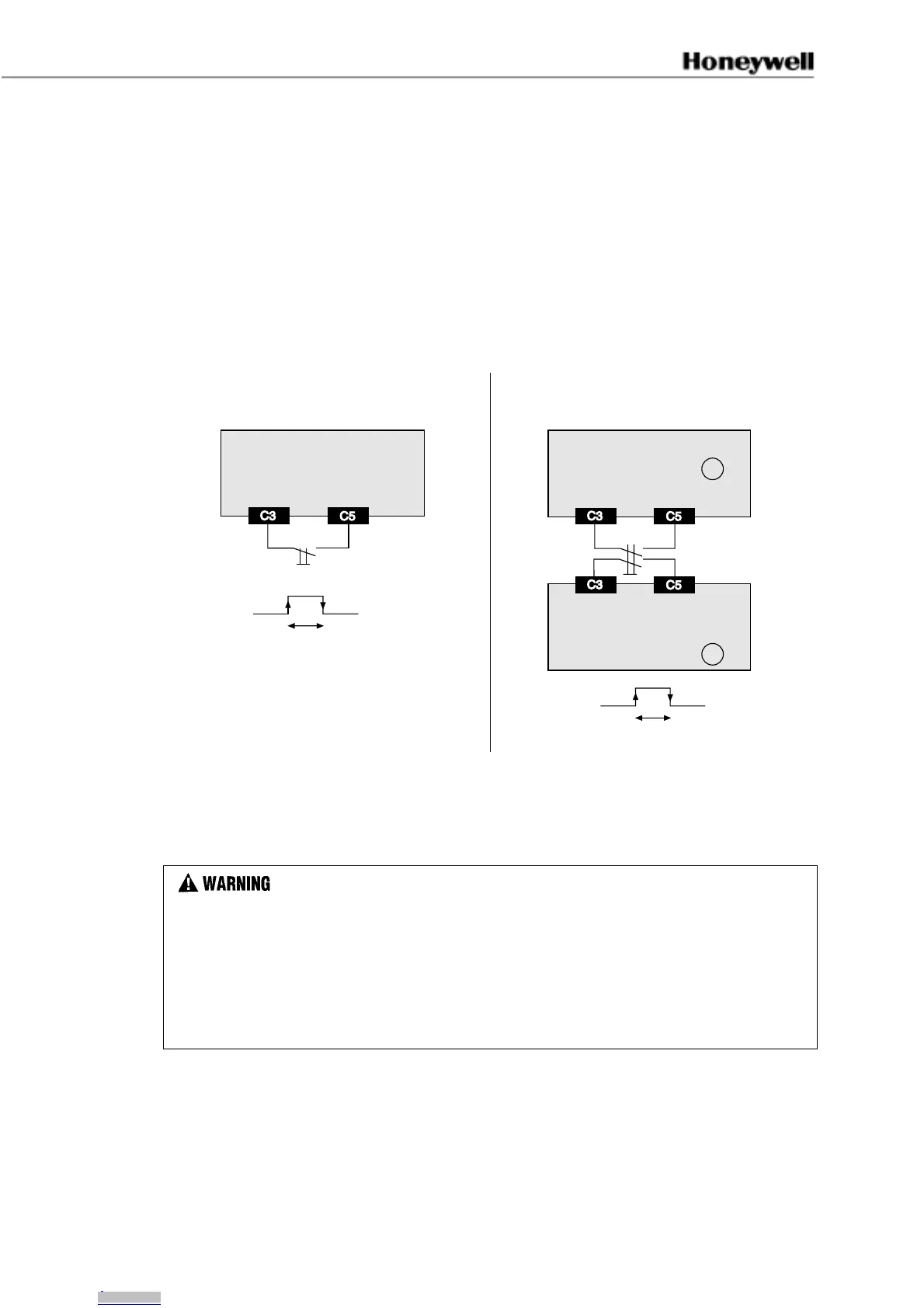
Start and Restart (Cycle) Interlock Mode of Operation
The start and restart interlock mode of operation causes the system to remain in an alarm
condition after power up or a beam interruption. To restart the equipment, a normally open
(N.O.) contact of a push button (P/B) or manual restart must be actuated (see figure 2-10).
Figure 2-10 Wiring Diagram of one single
beam
Figure 2-11 Wiring Diagram of several
beams
FF-SPSR
50 mA/12 Vdc
100 ms < t < 3.4 s
FSP43
50 mA/12 Vdc
FF-SPSR
B
50 mA/12 Vdc
FF-SPSR
A
100 ms < t < 3.4 s
FSP44
To restart the perimeter safety system, press and release the P/B within the specified time
frame. If the P/B is not pushed, the safety system remains in an alarm condition. Restart is
only possible if the sensing beam is not interrupted (no object is present). A short press and
release of the P/B is enough to restart the system. The safety system restarts after the release
of the push-button.
IMPROPER PERIMETER PROTECTION
• Design control circuit to allow a manual restart before further machine operation can occur.
• Locate manual restart outside of danger zone where operator has a clear view of zone.
• Operator should NOT be able to reach manual restart from within danger zone.
• Design control circuit to prevent Programmable Logic Controller from overriding manual
restart.
• Install two FF-SPS4 perimeter devices (two beam minimum) per safety application.
Failure to comply with these instructions could result in death or serious injury.
The FF-SPS4 Series perimeter guarding system is factory set (see figure 2-12) to operate in
the start and restart interlock mode to control access to a dangerous zone. The restart push-
button must be installed outside the dangerous area. If an application requires an alternate
mode of operation (start interlock and automatic reset), consult the Application Center for
additional information.
Downloaded from Arrow.com.Downloaded from Arrow.com.Downloaded from Arrow.com.Downloaded from Arrow.com.Downloaded from Arrow.com.Downloaded from Arrow.com.Downloaded from Arrow.com.Downloaded from Arrow.com.Downloaded from Arrow.com.Downloaded from Arrow.com.Downloaded from Arrow.com.Downloaded from Arrow.com.Downloaded from Arrow.com.Downloaded from Arrow.com.Downloaded from Arrow.com.Downloaded from Arrow.com.Downloaded from Arrow.com.Downloaded from Arrow.com.Downloaded from Arrow.com.Downloaded from Arrow.com.Downloaded from Arrow.com.Downloaded from Arrow.com.Downloaded from Arrow.com.Downloaded from Arrow.com.Downloaded from Arrow.com.Downloaded from Arrow.com.Downloaded from Arrow.com.Downloaded from Arrow.com.Downloaded from Arrow.com.Downloaded from Arrow.com.
 Loading...


