152 MS-5UD & MS-10UD Series Manual — P/N 52626:C2 1/24/2012
Appendix C: FACP with Keltron
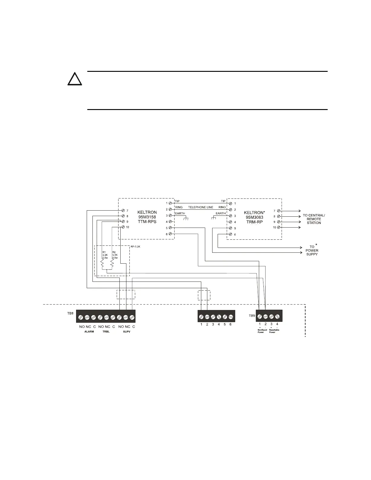
The following figure illustrates the connections between the FACP and Keltron Receiver/Transmit-
ter.
IMPORTANT! All connections between the FACP and Keltron modules must be made within 20
feet and enclosed within conduit or equivalently protected against mechanical injury.
P
CAUTION: POSSIBLE EQUIPMENT DAMAGE
FOR REASONS OF WIRING DIAGRAM CLARITY, TERMINAL DESIGNATIONS OF KELTRON
MODULES ARE NOT SHOWN IN ACTUAL ORDER. FOLLOW KELTRON MANUAL AND
MODULE MARKINGS FOR EXACT TERMINAL LOCATIONS TO PREVENT SEVERE MODULE
DAMAGE!
Fire Alarm Control Panel
(terminal blocks are not shown in their
actual positions in order to clarify wiring
connections)
Keltron 95M3158 TTM-RPS
1. Terminals 7 and 8: Remote station alarm/trouble inputs.
2. Terminals 9 and 10: Sprinkler supervisory input.
Note: Cut TBL jumper on 4XTMF module to send
alarm/trouble signal from the same pair or terminals.
Alarm/Trouble SignalSprinkler Supervisory Signal
*Note: For more
information, refer to the
Keltron manual.
4XTMF Module
Figure C.1 Keltron Wiring

 Loading...


