MS-5UD & MS-10UD Series Manual — P/N 52626:C2 1/24/2012 39
Installation of Optional Modules Installation
2.7.2 4XTMF Option Module
The 4XTMF module can be plugged into connectors J4 and J5 on the main circuit board.
The following steps must be followed when installing the 4XTMF module:
1. Remove all power (AC and DC) from the FACP before installing the modules.
2. Cut jumper JP30 on the main circuit board to allow the control panel to supervise the
placement of the 4XTMF option module.
3. Install the two supplied metal standoffs in the locations indicated. These standoffs provide the
required earth ground protection.
4. Carefully plug the connectors on the option module into connectors J4 and J5 on the FACP
main circuit board, being careful not to bend any pins.
5. Secure the option module to the standoff on the main circuit board with the supplied screws.
6. For proper 4XTM operation, the output relays must be programmed for the factory default
settings: Alarm Relay 1, Trouble Relay 2 and Supervisory Relay 3.
7. When the installation has been completed, connect the wiring to the modules as indicated in
the following sections.
8. Test system for proper operation.
4XTMF Transmitter Module Installation
The 4XTMF provides a supervised output for a local energy municipal box transmitter in addition
to alarm and trouble reverse polarity. A jumper option allows the reverse polarity circuit to open
with a system trouble condition if no alarm condition exists. A disable switch allows disabling of
the transmitter output during testing to prevent accidental calling of the monitoring service.
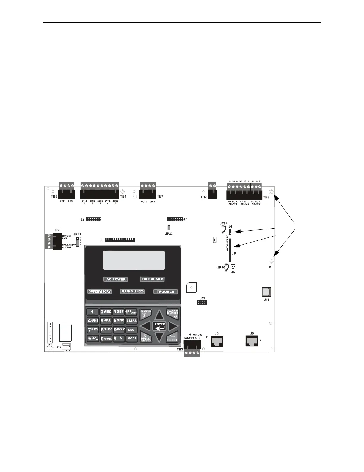
Figure 2.16 4XTMF Option Module Connection to MS-5UD
J4
J5
Standoffs
ms-5board.wmf
Note: This illustration shows the installation of the Option Module on the 5-zone panel.
The module is installed in the same location on the 10-zone panel.

 Loading...


