MS-5UD & MS-10UD Series Manual — P/N 52626:C2 1/24/2012 41
ANN-BUS Devices Installation
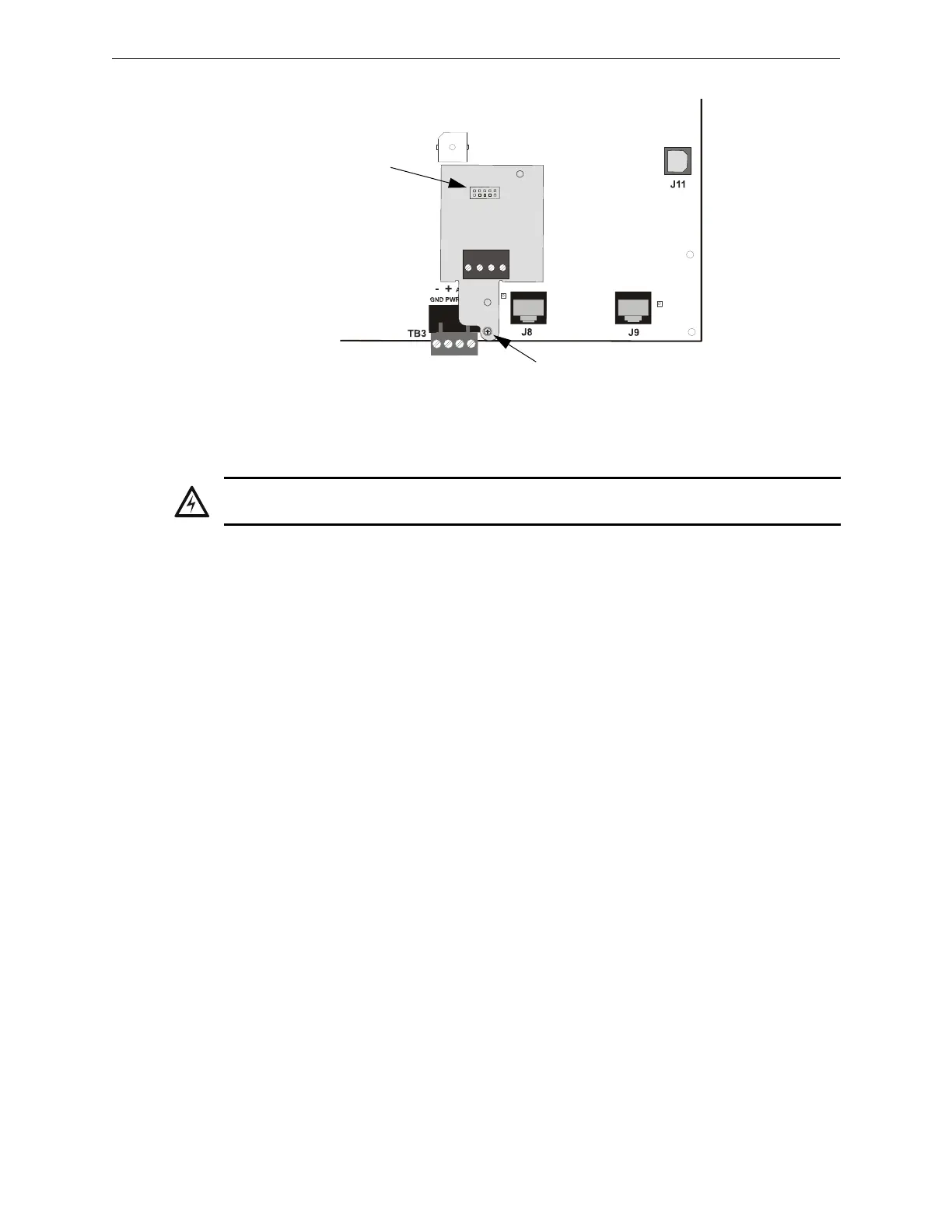
3. Secure the ANN-SEC to the circuit board with the supplied screw.
2.8 ANN-BUS Devices
Guidelines
• A variety of optional annunciation devices can be connected to an ANN-BUS communication
circuit. ANN Series devices can be connected to the primary communication circuit (EIA-485)
terminals on TB3. A secondary communication circuit (EIA-485) for these devices is available
at TB1 on the ANN-SEC card.
• When using one ANN-BUS circuit, up to eight (8) annunciators can be supported.
• When using both ANN-BUS communication circuits, the primary circuit supports up to three
(3) annunciators and the secondary circuit supports up to (5) annunciators.
Compatible devices include:
– ANN-80 LCD Annunciator
– ANN-80C LCD Indicator (Canadian Applications)
– ANN-S/PG Serial/Parallel Printer Interface Module
– ANN-I/O LED Driver Module
– ANN-LED Annunciator Module
– ANN-RLY Relay Module (can be mounted in the FACP chassis)
• When operating two ANN-BUS circuits, only one ANN-S/PG Printer module can be used in
the system.
• The panel is capable of operating a primary ANN-BUS (TB3) and a secondary ANN-BUS
(TB1 on ANN-SEC card) simultaneously.
2.8.1 ANN-BUS Wiring
This section contains information on calculating ANN-BUS wire distances and the types of wiring
configurations (Class B). The length of the 4-conductor wire run is governed by the power pair
loading as described below.
Calculating Wiring Distance for ANN-BUS Modules
The following instructions will guide the installer in determining the type of wire and the maximum
wiring distance that can be used with FACP ANN-BUS accessory modules.
ANN-SEC
FACP Circuit Board
connector to J13 on
main circuit board
standoff and screw
Figure 2.18 Installing the ANN-SEC Option Card
ann-secinst.wmf
WARNING: RISK OF ELECTRICAL SHOCK
Disconnect all sources of power (AC and DC) before installing or removing any modules or wiring.

 Loading...


