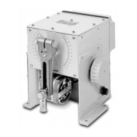
10260A Series Actuators Installation, Operations, and Maintenance Manual
8 10260A Series Actuators – Installation, Operations, and Maintenance 2/03
Physical
Output Torque/Full Travel
Stroking Time
Model #
10261A
10262A
10264A
10266A
10267A
10268A
10269A
10263A
10265A
Torque
Lb.-ft N-M
10 15
20 27
40 55
60 80
40 55
80 110
150 200
200 270
300 400
Output Shaft Speed sec/90°
@ 60Hz @ 50Hz
10 12
20 24
40 48
60 72
20 24
40 48
60 72
40 48
60 72
Electrical
Power Input 120 Vac single phase, 50 or 60 Hz
240 Vac single phase, 50 or 60 Hz
Motor Instant start/stop, non-coasting, non-burnout, continuous duty permanent magnet
synchronous induction motor. Can be stalled up to 100 hours without damage.
Motor Current = No load = full load = locked rotor
Model No.
10261A, 62A, 64A, 66A
10263A, 10265A
10267A, 68A, 69A
120 V, 50/60 Hz
0.4 A (48 VA)
1.0 A (120 VA)
0.8 A (96 VA)
240 V, 50/60 Hz
0.3 A (24 VA)
1.0 A (60 VA)
0.3 A (36 VA)
Loss of Power Stays in Place
Local Auto/Manual Switch Optional - allows local and automatic operation of the actuator.
Limit Switches Standard - Two SPDT end of travel limits rated (10 A at 125 Vac, 5 A at 250 Vac).
Auxiliary Switches Optional - Up to 4 additional SPDT switches rated (10 A at 125 Vac, 5 A at 250 Vac)
Certifications
CE Compliance 89/336/EEC EMC Directive, 73/23/EEC Low Voltage Directive.
NEMA 4 Optional
Torque Settings of Crank Arm Bolts
Clamp Bolt Standard Arm (p/n 087449) (1-7/16–5 in. adjustment): 85 lb.-ft.
Optional Long Arm (p/n 154007) (0–12 in. adjustment): 85 lb.-ft.
Rod End Bolt Standard and long arms: 30-35 lb.-ft

 Loading...


