NCD Instruction Manual — P/N LS10210-051NF-E:C 2/18/2019 13
CAB-4 Series Cabinet Installation
2.3 CAB-4 Series Cabinet
This section provides instructions for mounting the CAB-4 Series backbox to a wall. Follow these guidelines when mounting the back-
box:
Locate the cabinet backbox on a surface that is in a clean, dry, vibration-free area. The top should be located so that all operational but-
tons, switches, displays, etc. are easily accessible and/or viewable to the operator - usually no more than 66 inches (1.7m.) above the
floor. Allow sufficient clearance around the cabinet for the door to swing freely, and for easy installation and maintenance of equipment.
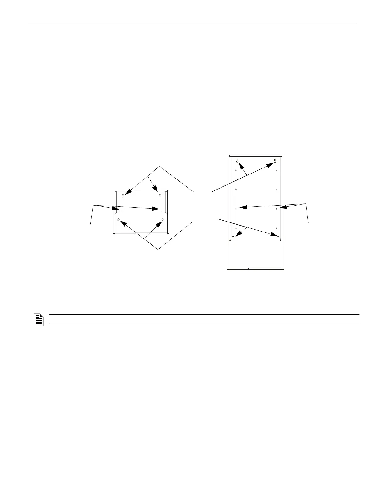
• Use the four holes in the back surface of the backbox to provide secure mounting (See Figure 2.2, “Backbox-Mounting Holes and
chassis-Mounting Studs” on page 13).
• Mount the backbox on a surface that is in a clean, dry, vibration-free area.
• Mark and pre-drill holes for the top two keyhole mounting bolts.
• Select and punch open the appropriate knock-outs.
• Using the keyholes, mount the backbox over the two screws.
• Mark the location for the two lower holes, remove the backbox and drill the mounting holes.
• Mount the backbox over the top two screws, then install the remaining fasteners. Tighten all fasteners securely.
• Feed wires through appropriate knockouts.
• Install NCD and other components according to this section, before installing hinges and door (see CAB-3/CAB-4 Series Cabinet
Installation Document).
Figure 2.2 Backbox-Mounting Holes and chassis-Mounting Studs
2.4 Installing the NCD on ONYX Series panels.
Mounting the NCD on the NFS2-3030
The NFS2-3030 CPU mounts in the CHS-M3 chassis located in the top row of the cabinet. The CPU will occupy the left half of the
chassis.
When using the NCD as a primary display, the NFS2-3030 CPU will need to be remounted with shorter 1/4 inch standoffs (PN 42138)
included with the NCD.
The NCD can be directly connected to the NUP port of the CPU2-3030.
When using the NCD as an alternate display on a standard Noti•Fire•Net, the panel becomes standalone and is not networkable, since
there is only one NUP port available on the NCM. If the panel is on a High-Speed Noti•Fire•Net, the panel can be networked using the
second NUP available on the HS-NCM.
The NFS2-3030 CPU should be installed according to Figure 2.3 to accommodate the NCD. If this is a retrofit, you will need to remove
the LCD Display, Keypad, and Header Pins. The CPU will be reinstalled in slot 3.
To install the NFS2-3030 CPU do the following:
• Attach three standoffs (PN 42138) to chassis as shown in
• Slide circuit-board tabs into slot 3 on the chassis.
• Place the board over the stand-offs so that mounting holes line up with those on the chassis. Secure all stand-offs with screws
provided.
• The NCD will be mounted to the dress plate, see “Dress Plate Mounting” on page 16 for more information.
Keyholes
2 places
Mounting holes
2 places
CAB-4 Series backbox,
A-size (one-row)
CAB-4 Series
backbox,
D-size (four-
row)
Chassis-
mounting
studs
(2 per row of
backbox)
Chassis-
mounting
studs
(2 per row of
backbox)
NOTE: The Network Control display (NCD) must be installed in position one on the LEFT side of the CHS-MS for NFS2-3030 mounting
 Loading...