NCD Instruction Manual — P/N LS10210-051NF-E:C 2/18/2019 17
Board Layout and Wiring Requirements Installation
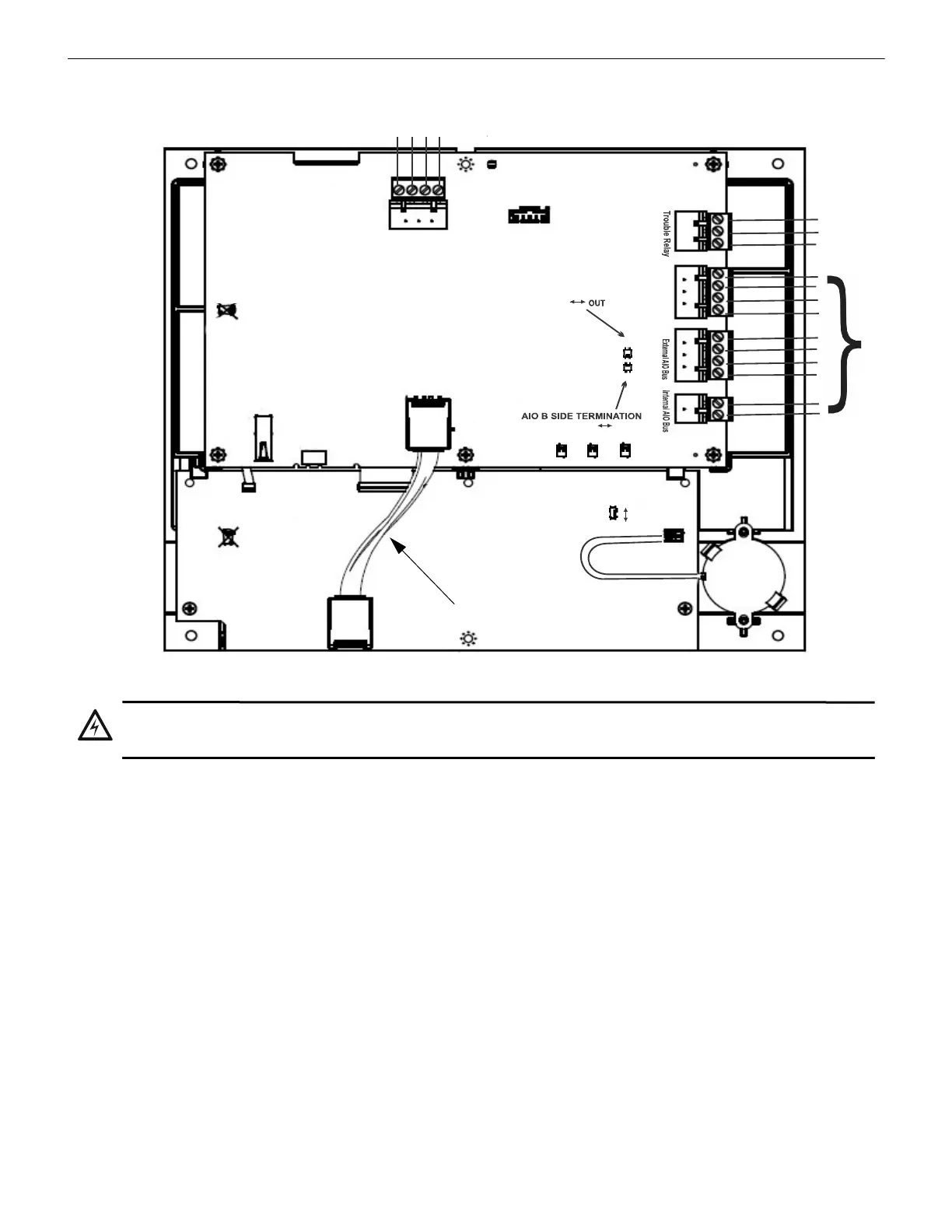
2.6 Board Layout and Wiring Requirements
Figure 2.6 Board Layout and Wiring Requirements
P
r
i
n
t
e
r
Alt. 24V Power
IN
OUT
-
-
+
N/O
N/C
COM
SW1
SW2
Tamp er
J7
J8
J9
J6
J10
J11
J12
J1
J3
USB A
USB B Micro
Piezo Enable/disable
Core Board
DIM
Board
Disable
Enable
NUP
OCuLink Cable
Future Use
Future Use
WARNING: DO NOT CONNECT OR DISCONNECT THE OCULINK CABLE BETWEEN THE CORE AND DIM
BOARDS (UPPER AND LOWER BOARDS) WHILE POWER IS APPLIED TO PREVENT SYSTEM DAMAGE.
 Loading...