18 NCD Instruction Manual — P/N LS10210-051NF-E:C 2/18/2019
Installation Board Layout and Wiring Requirements
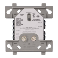
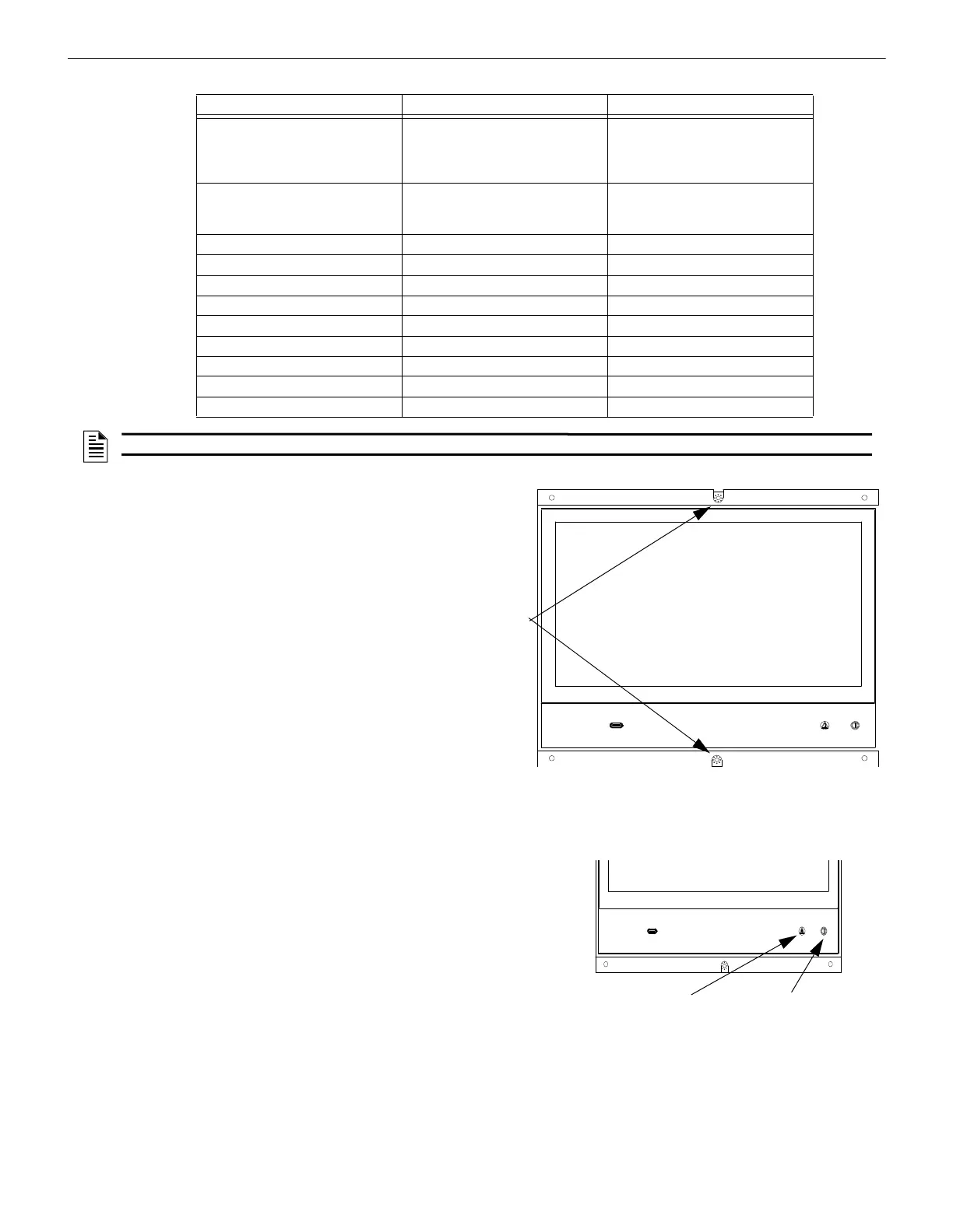
Ground Screw Locations
Ground screws are located at the center top and bottom cen-
ter on the front of the NCD. It is important to secure each
screw to maintain proper grounding. See Figure 2.7
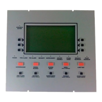
Event Indicator Locations
There are two LED indicators located on the bottom right of the NCD front
panel. A power LED to indicate if A/C is present, and an off normal LED for
any off normal condition. See Figure 2.8
Designator Connection Wire Connections
TB1
REQUIRED
Alt 24 Volt Power Pin 1 = IN+
Pin 2 = IN-
Pin 3 = OUT+
Pin 4 = OUT-
TB2 Trouble Relay Pin 1 = Normally Open
Pin 2 = Normally Closed
Pin 3 = Common
J10 NUP Connection Keyed
J11 USB A N/A
J12 USB Micro N/A
J7 Trouble Input
J8 Tamper Input
J9 Future Use Future Use
TB3 Future Use Future Use
TB4 Future Use Future Use
TB5 Future Use Future Use
NOTE: 24VDC is required to power the NCD (TB1 located on the NCD).
Ground
Screws
Figure 2.7 Ground Screw Locations
NCD Assembly
Off Normal LED Power LED
Front View of NCD
Figure 2.8 LED Locations
USB C
 Loading...