RP-2002 Series Manual — P/N 53039:E6 1/26/2017 121
Template 7: Cross-Zone System - Bell/Horn/Strobe FACP Configuration Templates
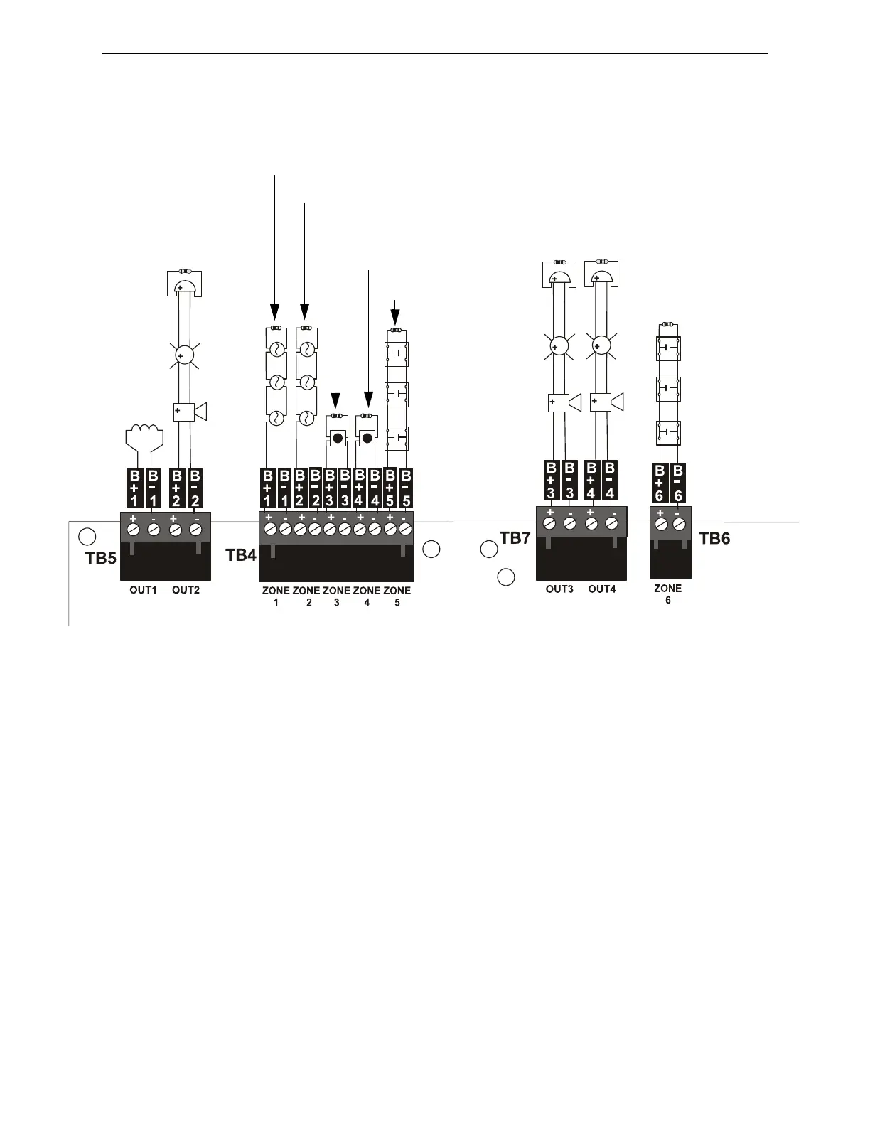
Device Installation Example for Template 7
Notes:
1. All End-of-Line Resistors, illustrated in this example, are 4.7KΩ, ½ watt (PN: 71252).
2. All devices are connected as Class B circuits. For details on connecting as Class A circuits,
refer to “N-CAC-5X Class A Converter Module” on page 31.
Output Circuit #2
Alarm NAC
Input Circuit #1
2-Wire Smoke
Input Circuit #3
Manual Release
Input Circuit #4
Abort Switch
Input Circuit #5
Discharge Pressure
Output
Circuit #1
Release
Solenoid 1
Input Circuit
#6
Supervisory
Output
Circuit #4
Release
Stage
Discharge
NAC
Input Circuit #2
2-Wire Smoke
agenttemp5.cdr
Output
Circuit #3
Release
Stage
Coded
NAC

 Loading...


