1. Introduction
1.5. About the transmitter
4 SmartLine Wireless Temperature and Universal I/O User's Manual Revision 1
STUW750
Channel 1 Channel 2 Channel 3
T/C or mV or DI or 2-wire
resistance or current
(0/4-20mA)
T/C or mV or DI or 2-wire
resistance or current
(0/4-20mA)
T/C or mV or DI or 2-wire
resistance or current
(0/4-20mA)
STUW751
Channel 1 Channel 2 Channel 3
T/C or mV or DI or 2-wire
resistance or current
(0/4-20mA)
T/C or mV or DI or 2-wire
resistance or current
(0/4-20mA)
DO
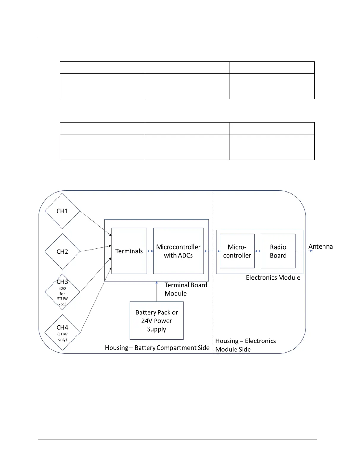
Figure 1-1 - SmartLine Wireless Transmitter Functional Diagram

 Loading...


