4.1 Mounting ST 3000 Transmitter, Continued
Precautions for
Mounting
Transmitters with
Small Absolute or
Differential Pressure
Spans, continued
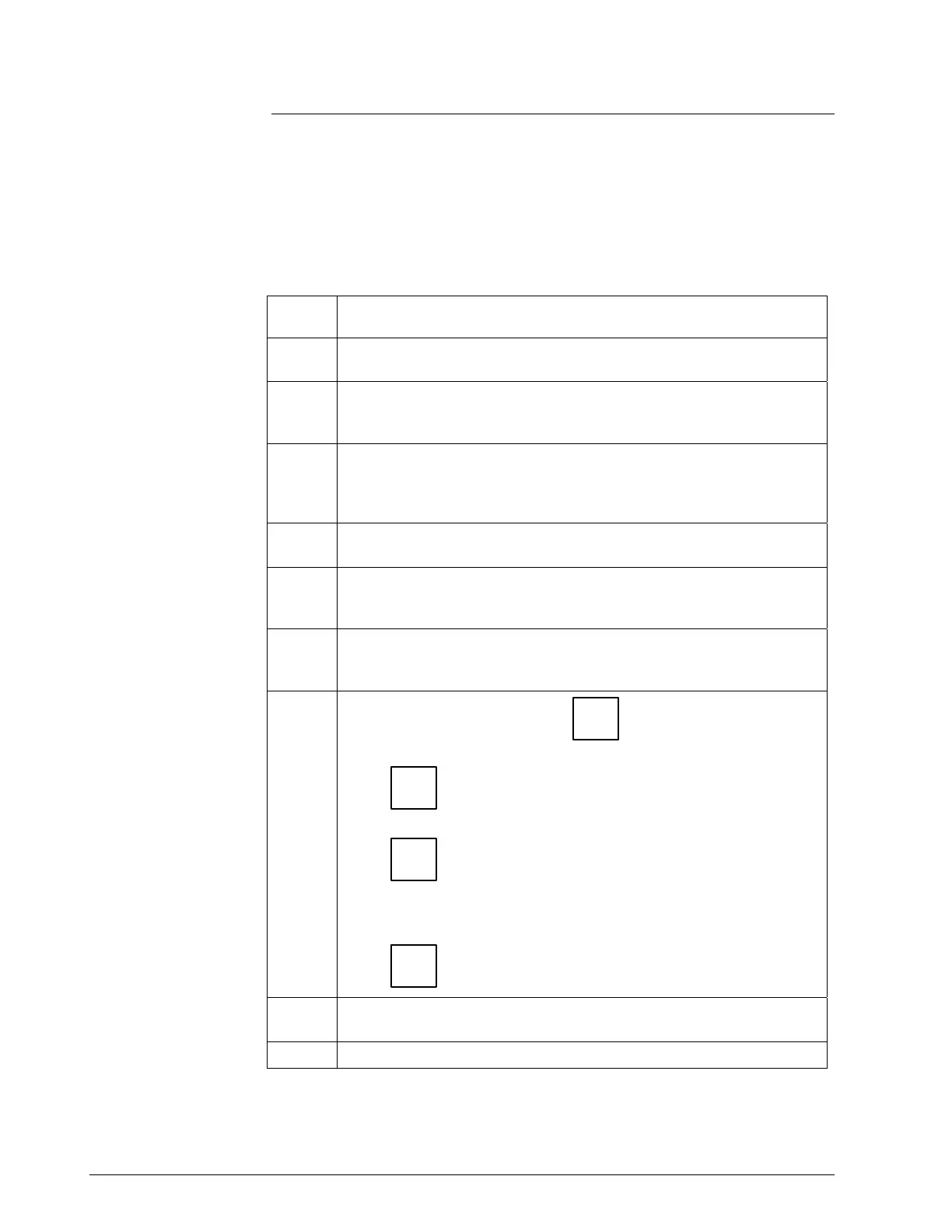
For a transmitter with a small differential pressure span, you must
ensure that the transmitter is vertical when mounting it. You do this by
leveling the transmitter side-to-side and front-to-back. See Figure 6 for
suggestions on how to level the transmitter using a spirit balance. You
must also zero the transmitter by following the steps in Table 9 below.
Table 9 Zero Corrects Procedure for STD110
Step Action
1
Attach the transmitter to the mounting bracket but do not completely
tighten the mounting bolts
2
Connect a tube between the input connections in the high pressure
(HP) and low pressure (LP) heads to eliminate the affects of any
surrounding air currents.
3
Connect 24 Vdc power to the transmitter and connect a digital
voltmeter or SFC to read the transmitter’s output. See Figure 1 for
typical SFC connection or connect a voltmeter across the 250 ohm
resistor, if desired.
4
Use the SFC (or SCT) and establish communications with the
transmitter. Follow the steps in Table 2, if needed.
5
While reading the transmitter’s output on an SFC or a voltmeter,
position the transmitter so the output reading is at or near zero and
then completely tighten the mounting bolts.
6
Do an input zero correct function using the SFC and following the
steps below. This corrects the transmitter for any minor error that
may occur after the mounting bolts are tightened.
7
Initiate shift key selection. Press
^
SHIFT
key
Press
INPUT
J
OUT-
PUT
key. Read applied input pressure.
Press
RESET
K
COR-
RECT
key. Prompt asks if the applied input pressure equals
zero input. If it is zero input, go to next keystroke. If it is not, press
[
CLR] key to exit function and repeat keystrokes.
Press
NON-VOL
ENTER
(Yes)
key. Zero input is set equal to applied input pressure.
8
Remove the tube from between the input connections, the power,
and the digital voltmeter or SFC.
9
Continue with the remaining installation tasks.
Continued on next page
28 ST 3000 Release 300 Installation Guide 2/05

 Loading...


