EasyManuals Logo

Honeywell ST 3000 Installation Guide

Honeywell ST 3000
126 pages
To Next Page IconTo Next Page
To Previous Page IconTo Previous Page
Page #68 background imageLoading...
Page #68 background image
A.4 Setting Range Values (Local Zero and Span), Continued
Procedure, continued
Table A-3 Setting Range Values Using Local Zero and Span
Adjustments, Continued
Step Action
10
Wait 30 seconds so that changes have been copied to the
transmitter’s non-volatile memory.
11
Remove applied pressure and turn OFF transmitter power.
12
Replace end-cap on PWA side of electronics housing and tighten
lock.
13
Remove milliammeter from TEST terminals and replace end-cap and
tighten lock.
14
Turn ON transmitter power and check smart meter reading, if
applicable.
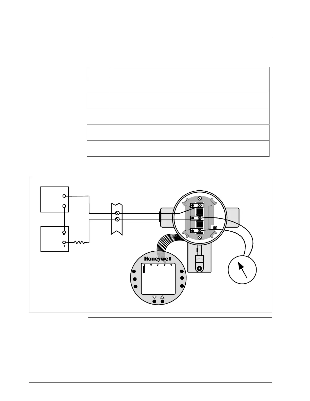
Figure A-2 Typical Setup for Setting Range Values Using Local Zero and Span Adjustments.
Smart Meter with
Local Zero and Span
installed on PWA side
of electronics housing
UPPER
VALUE
UNI T S
LOWER
VALUE
SET
VAR
SEL.
SPA N
ZERO
%
10 0
0
0
A
NALOG
In H O
2
00
-
S
I
G
N
A
L
+
+
-
T
E
S
T
Power
Supply
+
-
Receiver
+
-
Field
Terminals
ST 3000
250 ohm
Milliammeter
58 ST 3000 Release 300 Installation Guide 2/05

Table of Contents

Other manuals for Honeywell ST 3000

Questions and Answers:

Question and Answer IconNeed help?

Do you have a question about the Honeywell ST 3000 and is the answer not in the manual?

Honeywell ST 3000 Specifications

General IconGeneral
ManufacturerHoneywell
CategoryTransmitter
Stability±0.01% of URL per year
Operating Temperature-40 to 85°C (-40 to 185°F)
Communication ProtocolHART
Housing MaterialAluminum or Stainless Steel
Enclosure RatingIP66/67, NEMA 4X
Measurement TypeGauge, Absolute, Differential
Output Signal4-20 mA, HART
Process Temperature-40 to 121°C (-40 to 250°F)
Hazardous Area ApprovalsFM, CSA, ATEX, IECEx
Process Connection1/2" NPT
Material316L Stainless Steel, Hastelloy C

Related product manuals