About the System (cont’d)
8
Wiring
Connect the Tuxedo Touch in parallel with keypads and other peripheral devices using the keypad
data (ECP) bus.
• If the Tuxedo Touch is used as the primary system keypad, maximum wire run length is 150 feet.
• If more than one keypad is wired to one run, then the maximum lengths must be divided by the
number of keypads on the run. (e.g., the maximum length is 75 feet if two keypads are wired on a
#22 gauge run).
#22 gauge 150 feet
#20 gauge 240 feet
#18 gauge 350 feet
#16 gauge 550 feet
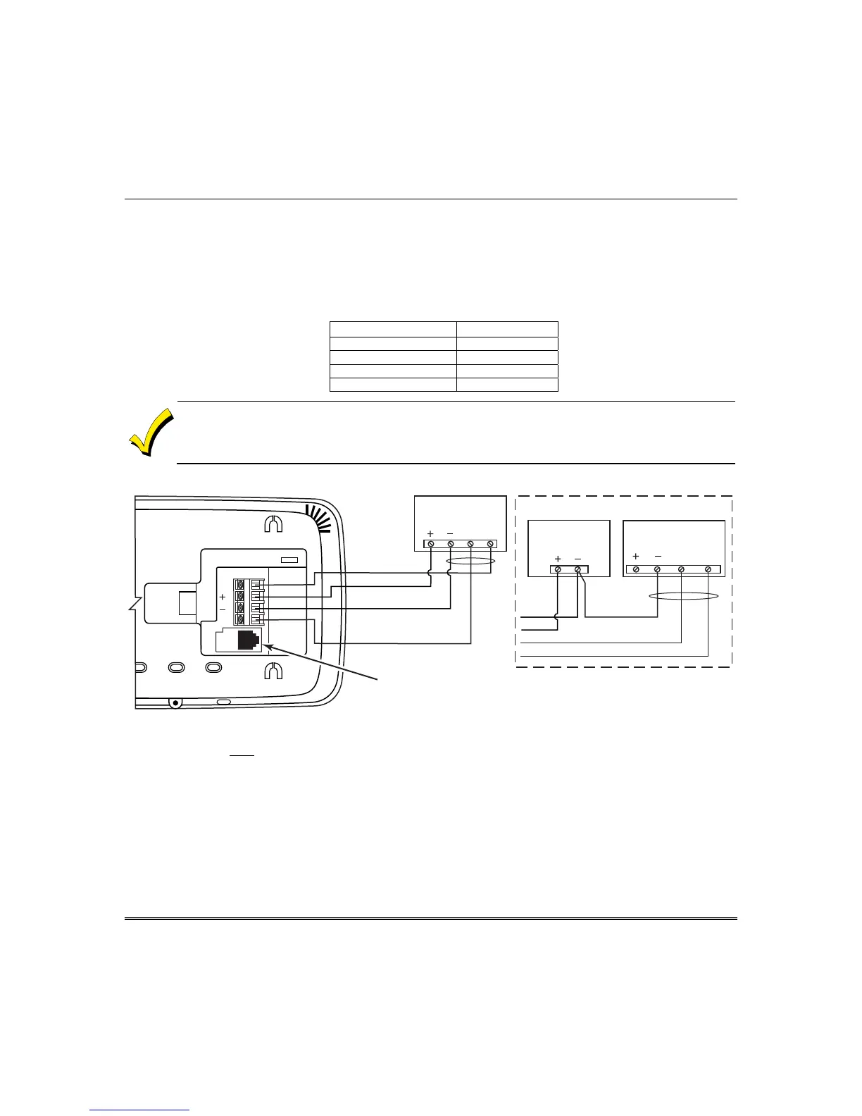
Connect the wires to the keypad terminal block as shown below.
6280WiFi-014-V1
BLACK
POWER FROM SUPPLEMENTARY
POWER SUPPLY IF USED
RED
BLACK
GREEN
YELLOW
CONTROL
TERMINAL STRIP
SUPPLEMENTARY
+12 VDC
POWER SUPPLY
P/N AD12612
BLACK (GND)
RED (+12VDC)
GREEN
( DATA TO
CONTROL)
YELLOW
(DATA FROM
CONTROL)
CONTROL
TERMINAL STRIP
AU X DATA
IN
DATA
OUT
AUX
DATA
IN
DATA
OUT
AUX
AUX
Y
G
IP CONNECTION
IMPORTANT: When the keypad is powered from an auxiliary power supply, always apply power to
the control panel first
and then the keypad. Failure to observe this sequence results in improper
operation of the keypad and may result in an ECP Error indication.
Installer Note: The Tuxedo Touch Screen has been calibrated at the factory. Ignore the “CALIBRATE”
button that appears on the “Options” screen after initial ECP setup. If the screen should require
recalibration, the end user may do so via the “Keypad Test” screen. See the “Diagnostic Tests” section
for instructions.
Supplementary external power supply must be Listed to UL603 for UL Burglary Installations and
UL1481 for UL Residential Fire Installations.
The Keypad draws up to 340mA for 9.6VDC, 260mA for 12VDC and 250mA for 13.8VDC.
If you power the keypad from your panel’s Aux Power output, check your panel’s Installation and
Setup Guide and verify that this device and others do not exceed your panel's Aux Power output
capability. If it does, a supplementary power supply is needed.

 Loading...