VISTA-128BPT/VISTA-250BPT Installation and Setup Guide
5-2
FIELD
TITLE and DATA ENTRIES EXPLANATION
∗
∗∗
∗09
Entry Delay #1 (partition-specific)
Enter 02-15 multiplied by 15 seconds.
00 = no delay.
Entry delay defines the delay time that allows users to re-enter the premises
through a door that has been programmed as an entry delay door and disarm
the system without sounding an alarm. The system must be disarmed within
this period or an alarm will occur.
NOTE: The delay may not exceed 45 seconds for UL installations.
∗
∗∗
∗10
Exit Delay #1 (partition-specific)
Enter 02-15 multiplied by 15 seconds.
00 = no delay.
Exit delay defines the delay period that allows users to leave the premises
through a door that has been programmed as an entry/exit delay door after
arming the system without setting off the alarm.
∗
∗∗
∗11
Entry Delay #2 (partition-specific)
Enter 02-15 multiplied by 15 seconds.
00 = no delay.
Entry Delay #2 is used for a secondary door requiring a longer delay than
those assigned to Entry Delay #1.
NOTE: The delay may not exceed 45 seconds for UL installations.
∗
∗∗
∗12
Exit Delay #2 (partition-specific)
Enter 02-15 multiplied by 15 seconds.
00 = no delay.
Exit Delay #2 is used for a secondary door requiring a longer delay than those
assigned to Exit Delay #1.
NOTE: The delay may not exceed 60 seconds for UL installations.
∗
∗∗
∗13
Alarm Sounder Duration (Bell
Timeout) (partition-specific)
Enter 01-15 multiplied by 2 minutes.
Defines the length of time the Bell Output and the keypad’s sounder will sound
for all audible alarms.
Must be minimum 16 minutes for UL Commercial Burglary installations.
∗
∗∗
∗14
RS232 Input
0 = Disable
1 = Enable
When enabled, sets RS232 input at TB4.
U
L
Using the RS232 input (TB4) for automation is not permitted in UL installations.
∗
∗∗
∗15
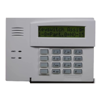
Keyswitch Assignment
Enter 1-8 partition keyswitch is being used.
Enter 0 if the keyswitch is not used.
The keyswitch requires the use of zone 7 wired loop (zone 7 is no longer
available as protection zone). The fire and panic alarm voltage triggers (J7)
automatically become ARMING and READY status outputs for the Keyswitch
LEDs.
Openings/closing report as user “0” if enabled in field ∗40.
∗
∗∗
∗16
Confirmation of Arming Ding
(partition-specific)
0 = disable
1 = enable
If enabled, produces ½-second external alarm sounding (“ding”) at the end of
exit delay (or after kissoff from the central station, if sending closing reports).
NOTE: If using a keyfob, when the button is pressed, either for arming or
disarming, the bell will ding indicating that the button is working.
Must be 1 for UL installations.
∗
∗∗
∗17
AC Loss Keypad Sounding
0 = disable
1 = enable
If enabled, sounding at the keypad (rapid beeping) occurs when AC power is
lost (sounding occurs about 2 minutes after actual AC loss).
∗
∗∗
∗19
Randomize AC Loss Report
0 = disable
1 = enable
If enabled, randomizes AC loss reporting between 10 and 40 min. after an
actual AC loss.
If disabled, AC loss reporting about 2 minutes after actual AC loss.
Selecting this option helps prevent an overload of AC loss messages at the
central station during a community blackout.
∗
∗∗
∗20
VIP Module Phone Code
1-9 = first digit of access code
∗ or # = second digit of access code (enter
11 for “∗”, or 12 for “#”)
To disable enter 00 for the 1
st
digit
Not Used.
Must be disabled for UL installations.
∗
∗∗
∗21
Prevent Fire Timeout
0 = disable (timeout)
1 = enable (no timeout)
If enabled, there is no timeout of the alarm sounder duration for all fire zones,
regardless of partition, so that fire sounding continues until the system is
reset.
If disabled, (timeout) the normal burglary sounder duration (field ∗13) applies
to fire alarms.
 Loading...

