EasyManua.ls Logo

HORNER HE-XE1E2 - Figure 11.8 - Universal Analog in Configuration Screen

Default Icon
158 pages
Print Icon
To Next Page IconTo Next Page
To Previous Page IconTo Previous Page
Loading...
MAN0878-09-EN_XLE_XLT_UserManual
A u g u s t 2 3 , 2 0 1 8 P a g e 78 | 158
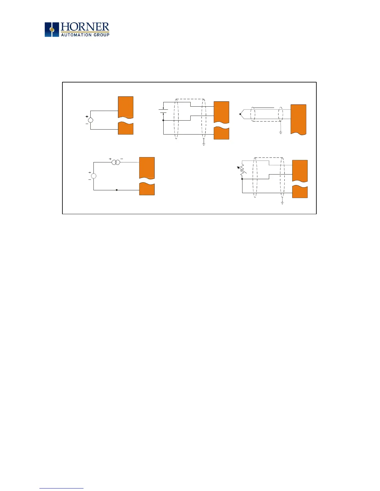
3. Ensure the proper wiring is used for each of the 3 pins A, B, and C on the
Universal Analog Inputs as seen in the reference image below.
Figure 11.8 Universal Analog In Configuration Screen
0 10 V Analog In
mV In
Thermocouple In
NC A1A
100mV+
A1B
100mV-
A1A
A1B
0-10VDC
A1C
A1A
A1B
A1C
A1C
20 mA Analog In
RTD In
20mA
A1A
A1B
LOOP PWR
A1C
A1B
A1C
A1A
NOTE:
Loop Power requirements are determined by the transmitter specification.

Table of Contents

Related product manuals