ILink
Interface
Data
is exchanged between
the
device
and
the
host
computer
through
the
link interface.
It
accepts
commands
from
the
microprocessor for
transmitting
and
receiving messages in
an
HP-
HIL frame format.
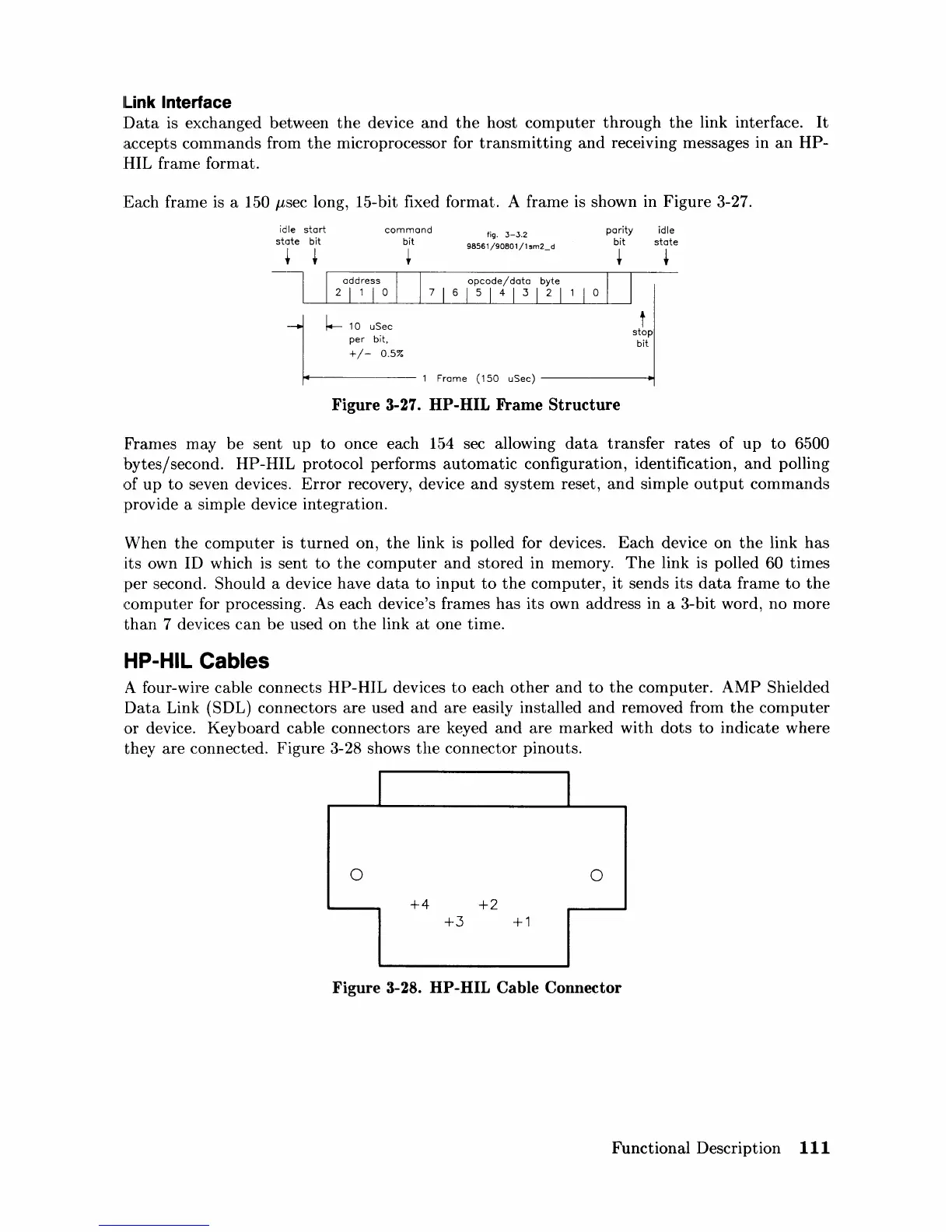
Each frame
is
a 150
J-lsec
long, 15-bit fixed format. A frame is shown in
Figure
3-27.
idle
start
st<Jte
bit
+ +
command
bit
per bit,
+/-
0.5%
+
fig.
3-3.2
98561/90801/1
sm2_
d
parity
idle
bit
state
+ +
t
stop
bit
1 Frame
(150
uSec)
------.1
Figure 3-27. HP-HIL Frame
Structure
Frames
m.ay
be
sent
up
to
once each 154 sec allowing
data
transfer
rates
of
up
to
6500
bytes/second.
HP-HIL
protocol performs
automatic
configuration, identification,
and
polling
IOf
up
to
seven devices.
Error
recovery, device
and
system
reset,
and
simple
output
commands
provide a simple device integration.
When
the
computer
is
turned
on,
the
link
is
polled for devices.
Each
device
on
the
link
has
its own ID which is sent
to
the
computer
and
stored
in memory.
The
link is polled 60 times
per second. Should a device have
data
to
input
to
the
computer,
it
sends
its
data
frame
to
the
computer
for processing. As each device's frames has its own address in a 3-bit word,
no
more
than
7 devices
can
be
used
on
the
link
at
one time.
HP-HIL Cables
A four-wire cable connects
HP-HIL
devices
to
each
other
and
to
the
computer.
AMP
Shielded
Data
Link (SDL) connectors
are
used
and
are easily installed
and
removed from
the
computer
or
device.
Keyboard
cable connectors
are
keyed
and
are
marked
with
dots
to
indicate
where
they
are
connected.
Figure
3-28 shows
the
connector pinouts.
0
0
+4
+2
+3
+1
Figure 3-28. HP-HIL Cable Connector
Functional Description
111

 Loading...