RAM Boards
Introduction
Model
330/350
RAM
boards
consists
of
one controller
board
and
two add-on
boards
listed in
Table 3-2.
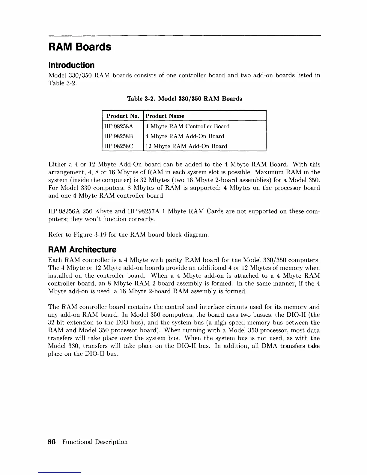
Table 3-2. Model 330/350 RAM Boards
Product No. Product Name
HP98258A
4 Mbyte RAM Controller Board
HP98258B 4 Mbyte RAM
Add-On Board
HP98258C
12
Mbyte RAM Add-On Board
Either
a 4
or
12
Mbyte
Add-On
board
can
be
added
to
the
4
Mbyte
RAM Board.
With
this
arrangement,
4,
8
or
16 Mbytes of
RAM
in each system slot is possible. Maximum RAM in
the
system (inside
the
computer)
is
32 Mbytes (two
16
Mbyte
2-board assemblies) for a Model 350.
For Model 330
computers,
8 Mbytes of RAM
is
supported;
4 Mbytes on
the
processor
board
and
one 4
Mbyte
RAM controller
board.
HP
98256A 256
Kbyte
and
HP
98257 A 1
Mbyte
RAM
Cards
are
not
supported
on these com-
puters;
they
won't
function correctly.
Refer
to
Figure
:3-19
for
the
RAM
board
block diagram.
RAM Architecture
Each
RAM
controller
is
a 4
Mbyte
with
parity
RAM
board
for
the
Model
330/350
computers.
The
4
Mbyte
or
12
Mbyte
add-on
boards
provide
an
additional 4
or
12
Mbytes
of
memory when
installed on
the
controller board.
When
a 4
Mbyte
add-on
is
attached
to
a 4
Mbyte
RAM
controller
board,
an
8
Mbyte
RAM 2-board assembly
is
formed. In
the
same
manner,
if
the
4
Mbyte
add-on
is
used, a 16
Mbyte
2-board
RAM
assembly is formed.
The
RAM
controller
board
contains
the
control
and
interface circuits used for its memory
and
any add-on
RAM
board.
In Model 350 computers,
the
board
uses two busses,
the
DIO-II
(the
32-bit extension
to
the
DIO
bus),
and
the
systern bus
(a
high speed memory bus between
the
RAM
and
Model 350 processor
board).
When
running
with
a Model 350 processor,
most
data
transfers will
take
place over
the
system bus.
When
the
system
bus
is
not
used, as
with
the
Model 330, transfers will
take
place on
the
DIO-II bus. In addition, all DMA
transfers
take
place on
the
DIO-II bus.
86
Functional Description

 Loading...