Chapter 3 Replacing Assemblies
To Remove A6 High Stability Timebase Assembly (Options 001, 010, and
012)
3-20 Assembly-Level Service Guide
3
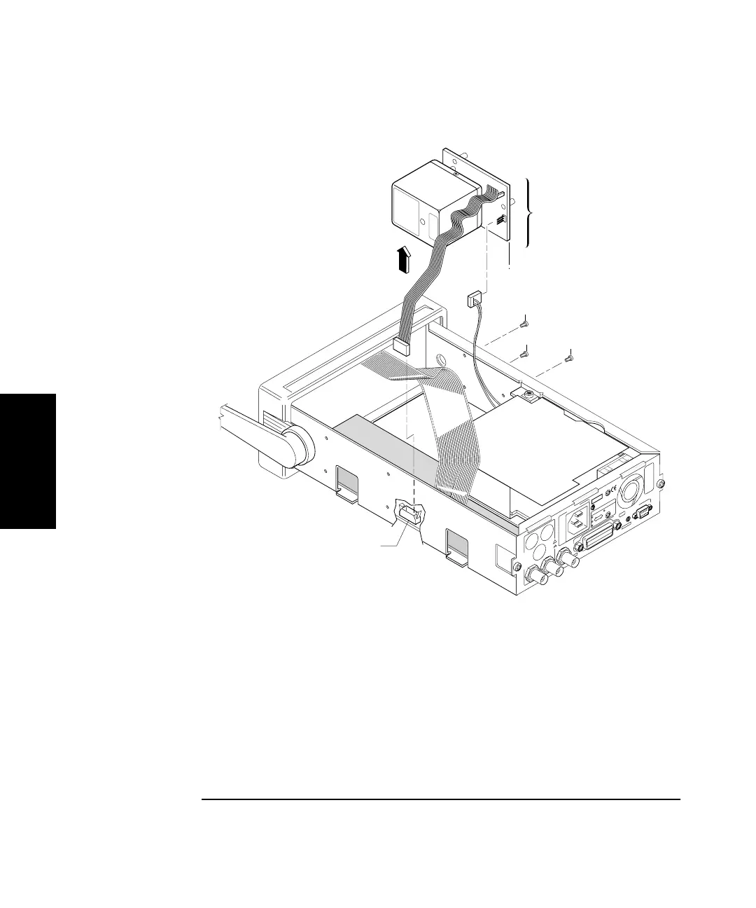
Figure 3-12. Option 001, 010, and 012 A6 High Stability Timebase
Assembly Removal
3 Disconnect the ac power supply’s two-wire cable from A6 High
Stability Timebase Assembly (if the two-wire cable exists).
4 Remove the three TORX 10 screws (H2) attaching the timebase to
the chassis as shown in Figure 3-12.
5 Remove A6 High Stability Timebase Assembly.
H2
H2
H2
1
Ext
Arm
Ref
In
I
N
P
U
T
S
!
AC LINE:
10 MHz Out
60 VA
100 - 120 VAC
200 - 240 VAC
50/60/400 Hz
50/60 Hz
OPTIONS
001 MS Oven
010 HS Oven
SERIAL PLATE
To Configure:
Hold Recall during turn-on.
Osc Adjust
RS - 232
ISM 1-A
92
FOR LABORATORY USE BY
QUALIFIED PERSONNEL
FOUR USAGE EN LABORATOIRE
PAR PERSONNEL QUALIFIE
HP-IB
Talk Only
2
3
A6 High Stability
Timebase Assembly
J9