9
7. Install cage nuts (user-supplied) in the mounting holes in the rack posts.
8. Place the switch on the rack shelf, push it into the rack until the brackets touch the rack posts, and
attach the mounting brackets with M6 screws (user-supplied) to the rack, as shown in Figure 5.
Rack-mounting by using front and rear mounting brackets
This installation method is available only for the 5500-24G-PoE+ EI (2 slots), 5500-24G-PoE+ EI TAA (2
slots), 5500-48G-PoE+ EI (2 slots), 5500-48G-PoE+ EI TAA (2 slots), 5500-24G-PoE+ SI (2 slots),
5500-48G-PoE+ SI (2 slots), 5500-24G-SFP EI (2 slots), and 5500-24G-SFP EI TAA (2 slots) switches.
This task requires two persons.
To install the switch in a 19-inch rack by using the front and rear mounting brackets:
1. Wear an ESD-preventive wrist strap and make sure it makes good skin contact and is well
grounded.
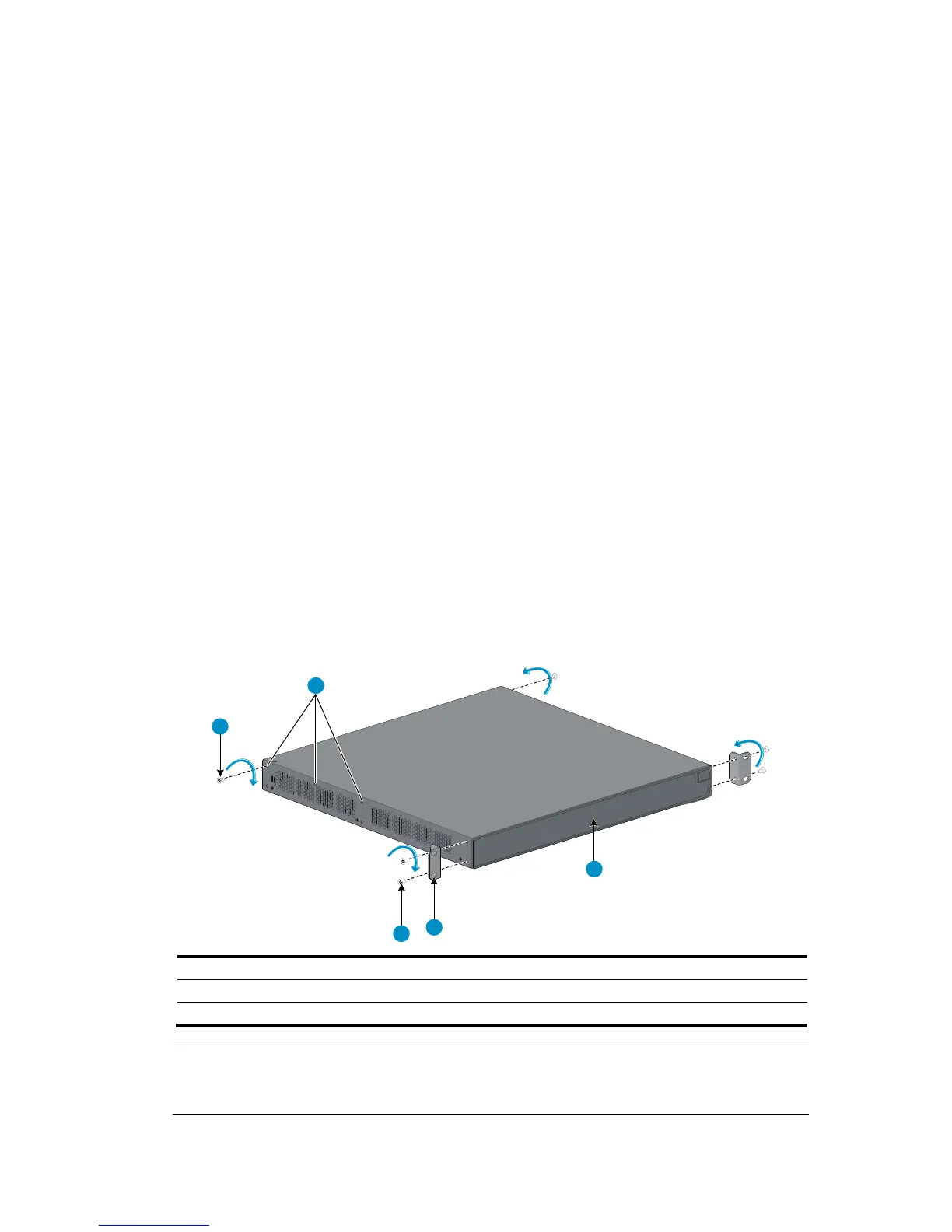
2. Unpack the front mounting brackets and the screws for attaching the brackets to the switch chassis.
3. Align the round holes in one front mounting bracket with the holes in the front mounting position of
the switch chassis, and use the removed screws to attach the mounting bracket to the chassis, as
shown in Figure 4.
4. R
epeat the previous step to attach the other front mounting bracket to the chassis.
5. Unpack the rear mounting brackets and the load-bearing screws.
6. Attach the load-bearing screws in one of the rear mounting positions (see callout 2 in Figure 6) a
s
needed.
The 5500-24G-SFP EI (2 slots) and 5500-24G-SFP EI TAA (2 slots) switches have only two of the
rear mounting positions.
Figure 6 Attaching the front mounting brackets and load-bearing screws to the switch chassis
1
2
3
4
5
(1) Load-bearin

 Loading...


