33
Figure 35 Use 2-port interface cards to set up multi-link IRF connection
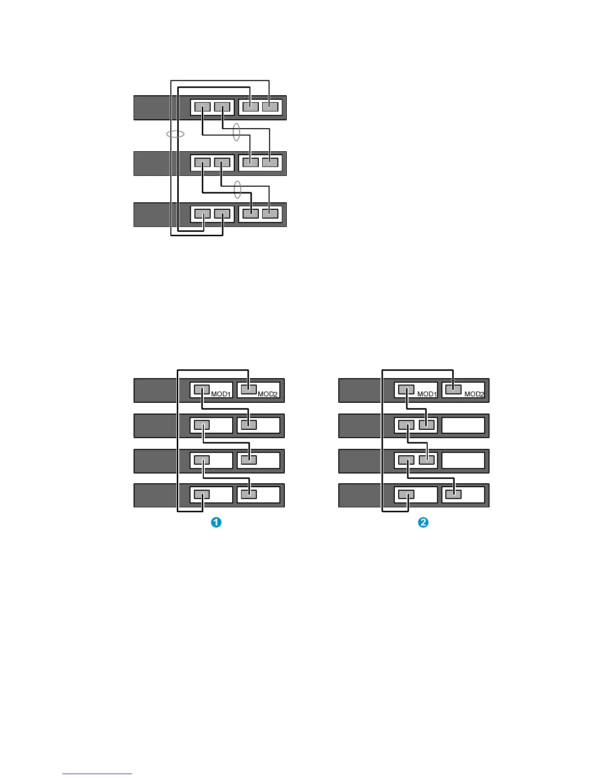
• If both of the neighboring switches use 1-port interface cards, the port on MOD 1 on one switch
must connect to the port on MOD 2 on the other switch (see callout 1 in Figure 36).
• If one switch uses a 1-port interface card but the other switch uses a 2-port interface card:
{ If the 1-port interface card is in the MOD 1 slot, the port on the card must connect to the right
port on the 2-port interface card (see callout 2 in Figure 36.)
{ If the 1-port interface card is in the MOD 2 slot, the port on the card must connect to the left port
on the 2-port interface card.
Figure 36 Cable connections for an IRF fabric with 1-port interface cards
Configuring basic IRF settings
After you install the IRF member switches, power on the switches, and log in to each IRF member switch
(see HP 5500 EI & 5500 SI Switch Series Fundamentals Configuration Guide) to configure their member
IDs, member priorities, and IRF port bindings.
Follow these guidelines when you configure the switches:
• Assign the master switch higher member priority than any other switch.
• Bind physical ports to IRF port 1 on one switch and to IRF port 2 on the other switch.
• Execute the irf-port-configuration active command to activate the IRF port configuration.
• Execute the display irf configuration command to verify the basic IRF settings.

 Loading...


