32
Identifying physical IRF ports on the member switches
Only the 10-GE ports on the IRF-capable interface cards listed in "Interface cards" can provide IRF
connections for the 5500 EI and 5500 SI switches. To use the IRF feature, you must order the cards
separately.
IMPORTANT:
one two-port interface card or two one-port interface cards.
Planning the cabling scheme
When you plan the cabling scheme, follow these guidelines:
• Ports assigned to the same IRF port must be on the same interface card.
• For long-distance connections, use XFP/SFP+ transceiver modules and fibers. For short-distance
connections, use CX4/SFP+ cables or twisted-pair cables. For more information, see "Interface
ca
rds" and "SFP/SFP+/XFP transceiver modules and SFP+/CX4 cables."
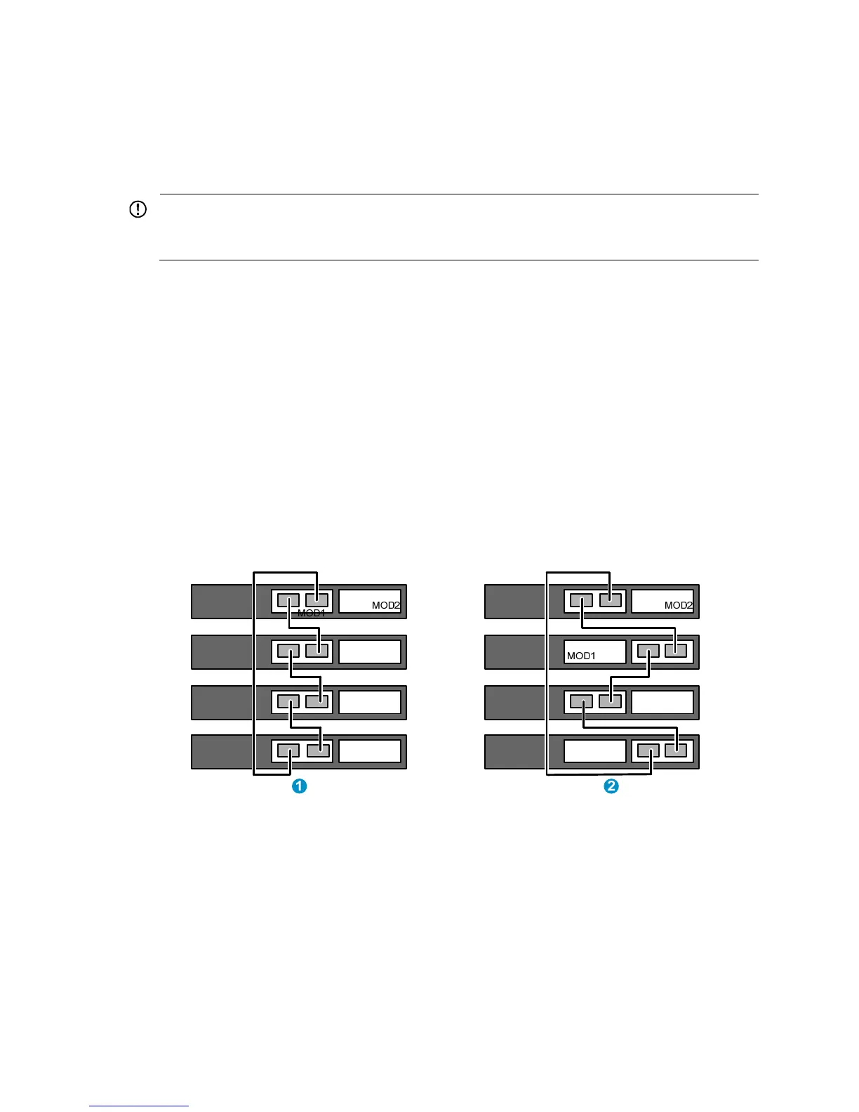
• If 2-port interface cards are used and the IRF links are not aggregate:
{ You can connect the interface card in slot 1 (MOD 1) on a member switch to the MOD 1 or
MOD 2 card on its neighboring switch.
{ Connect the left port on one interface card to the right port on the other interface card, as shown
in Figure 34.
Figure 34 Use 2-port interface cards to set up singl
e-link IRF connection
• If 2-port interface cards are used and IRF links are aggregate:
{
Connect the interface card MOD 1 on one switch to the interface card MOD 2 on the other
switch.
{ A port on one interface card can connect to any port on the other interface card, as shown
in Figure 35. F
or example, you can connect the left port on one interface card to the left or right
port on the other interface card.

 Loading...


