41
5500-24G-SFP EI (2 slots)/5500-24G-SFP EI TAA (2 slots)
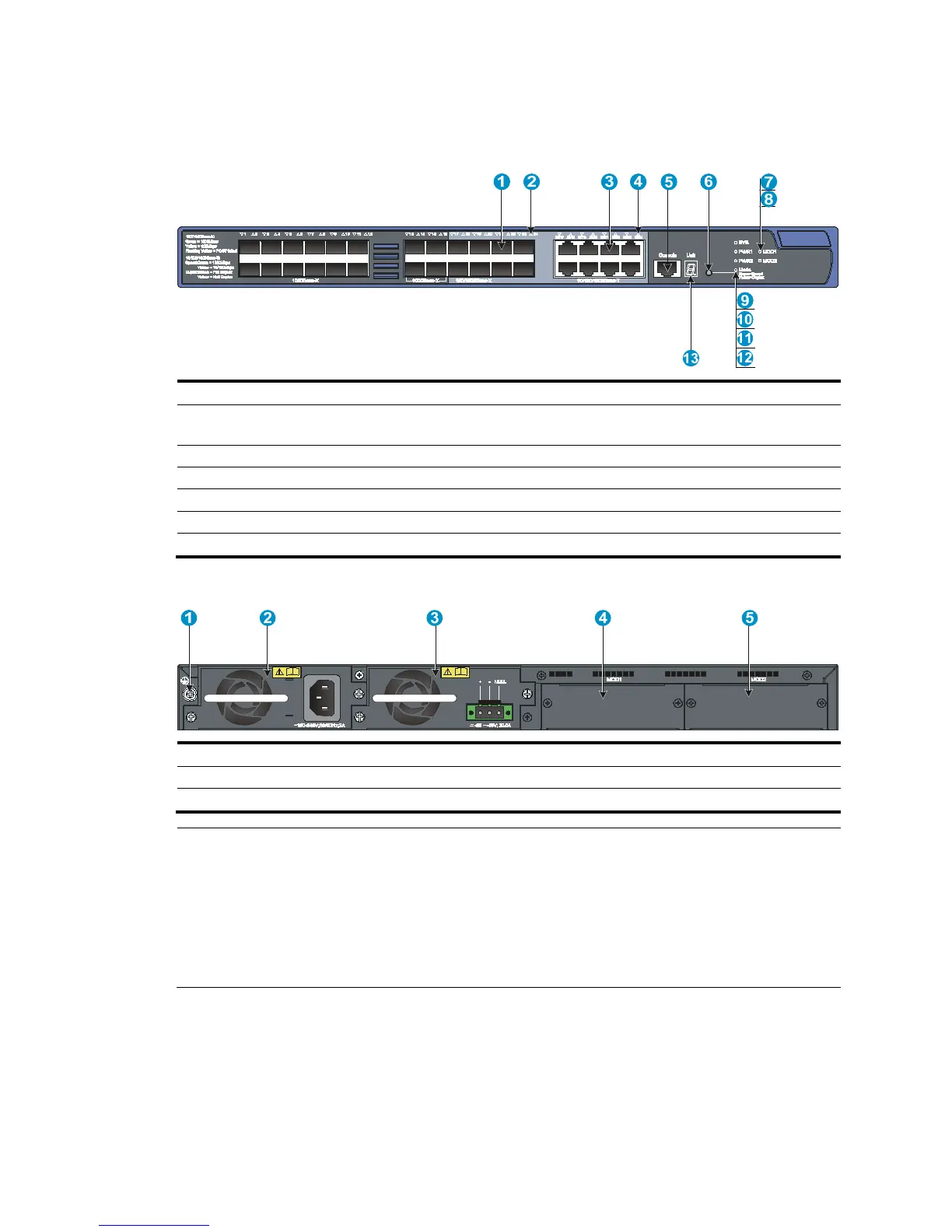
Figure 41 Front panel
(1) SFP port (2) SFP port LED
(3) 10/100/1000Base-T auto-sensing Ethernet
port
(4) 10/100/1000Base-T Ethernet port LED
(5) Console port (6)
button
(7) Interface card 1 status LED (MOD1)
Interface card 2 status LED (MOD2)
(9) System status LED (SYS) (10) Power supply 1 status LED (PWR1)
(11) Power supply 2 status LED (PWR2)
(12) Port mode LED (Mode)
(13) Seven-se
Figure 42 Rear panel
(1) Groundin
(3) Power supply slot 2 (4) Interface card slot 1
(MOD1)
(5) Interface card slot 2 (MOD2)
NOTE:
• The 5500-24G-SFP EI (2 slots) and 5500-24G-SFP EI TAA (2 slots) switches come with the expansion
interface card slots covered by filler panels.
• The 5500-24G-SFP EI (2 slots) and 5500-24G-SFP EI TAA (2 slots) switches come with one power
supply filler panel. If you use only one power supply, install the filler panel over the empty power suppl
slot to prevent dust and ensure normal ventilation of the chassis. In this figure, a PSR150-A is installed in
power supply slot 1 and a PSR150-D is installed in power supply slot 2.

 Loading...


