EasyManua.ls Logo

HP 5500 EI series - Page 16

HP 5500 EI series
69 pages
To Next Page IconTo Next Page
To Previous Page IconTo Previous Page
Loading...
11
Figure 8 Mounting the switch in the rack
1
2
3
4
(1) Rear panel (2) Rear square-holed post
(3) Load-bearin
g
screw (4) Rear mountin
g
bracket
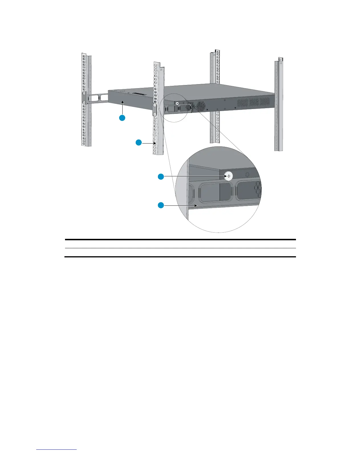
10. The other person aligns the oval holes in the front brackets with the mounting holes in the front rack
posts, and attaches the front mounting brackets with M6 screws (user supplied) to the front rack
posts, as shown in Figure 9.
Make sure the front and rear mou
nting brackets have securely attached the switch in the rack.

Table of Contents

Other manuals for HP 5500 EI series

Related product manuals