5-27. MARKER AND SAMPLER ADJUSTMENTS (UPDATES) (Cont'd)
6. Connect scope probe to A7TPl. Adjust A7 marker threshold potentiometers for the proper
pulse width of each marker as follows:
NOTE
The previous step calibrates
the
oscilloscope display to
100
kHz/
Division.
50 MHz: Adjust A7R5 (50M) for 600 kHz p-p
(6
divisions)
10 MHz: Adjust
A7R6
(10M)
for
400
kHz
pp
(4
divisions)
1
MHz:
Adjust A7R7
(1M)
for 200
kHz
p-p (2 divisions)
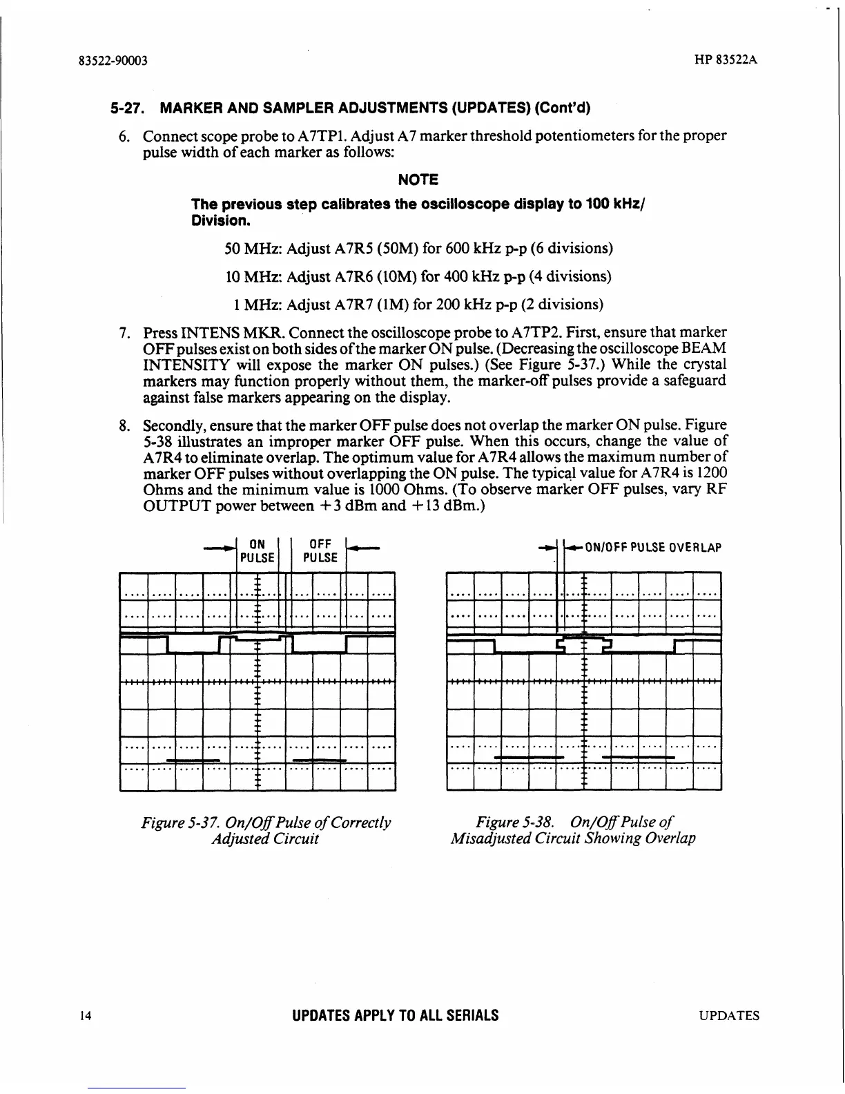
7.
Press INTENS
MKR.
Connect the oscilloscope probe to A7TP2. First, ensure that marker
OFF pulses exist on both sides of the marker ON pulse. (Decreasing the oscilloscope
BEAM
INTENSITY will expose the marker ON pulses.) (See Figure 5-37.) While the crystal
markers may function properly without them, the marker-off pulses provide a safeguard
against false markers appearing on the display.
8.
Secondly, ensure that the marker OFF pulse does not overlap the marker ON pulse. Figure
5-38 illustrates an improper marker
OFF'
pulse. When this occurs, change the value of
A7R4 to eliminate overlap. The optimum value for A7R4 allows the maximum number of
marker OFF pulses without overlapping the ON pulse. The typical value for
A7R4 is
1200
Ohms and the minimum value is 1000 Ohms. (To observe marker OFJ? pulses, vary RF
OUTPUT power between
+
3
dBm and
+
13 dBm.)
ONlOFF
PULSE
OVERLAP
....................
....................
....................
....................
Figure 5-3
7.
On/Off Pulse
of
Correctly Figure5-38. On/OfPulseof
Adjusted Circuit
Misadjusted Circuit Showing Overlap
UPDATES APPLY TO ALL SERIALS
UPDATES