Model
83522A
ADJUSTMENTS
Adjustments
5-25.
POWER SWEEP
REFERENCE:
Performance Test:
8350A Paragraph 4- 14.
Service Sheet: A5
DESCRIPTION:
A 10
dB/sweep power sweep mode is selected and the resultant is displayed on the 8755C
Swept Amplitude Analyzer. Output of the power sweep circuit is adjusted for the correct
sweep.
EQUIPMENT:
.....................................................
Sweep Oscillator HP 8350A
....................................
Swept Amplitude Analyzer.
HP
8755ClHP 182T
...........................................................
Detector. HP 11664A
.........................................
10 dB Attenuator.
HP
8491A Option 010
PROCEDURE:
NOTE
ALC gain adju-atments (paragraph 5-24) must be checked before power
sweep adjustment are made.
NOTE
This procedure assumes that A3S1 is set to the factory-set position (Table
5-6), and at the
8350A Sweep Oscillator, 27.8 kHz square wave modulation
is selected.
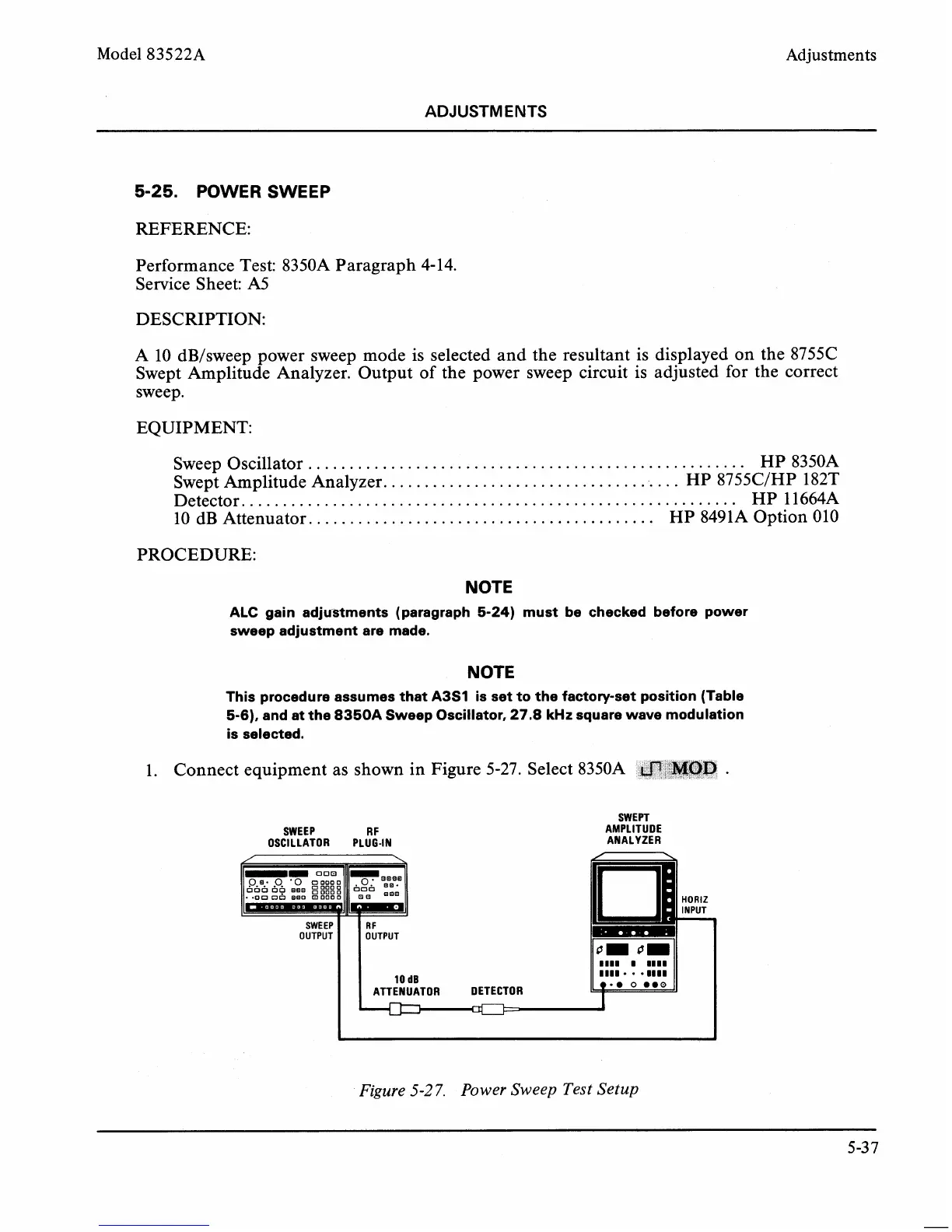
1.
Connect equipment as shown in Figure 5-27. Select
8350A
fli,fa&n
.
Figure
5-27.
Power Sweep
Test
Setup
SWEPT
SWEEP
R
F
AMPLITUDE
OSCILLATOR PLUG-IN ANALYZER
/
/
\
HORlZ
INPUT
-
0 0-
1111
1 1111
1111
1111
*we
0
0.0
I
oom
Q.?.
p.
-0
DO000
-m,",".Q
ooo
OF
s
:I:::
b~~b
.on
on
BQO
m
ooo
1
I
SWEEP
OUTPUT
RF
OUTPUT
10
dB
ATTENUATOR DETECTOR