Model 83522A Operation
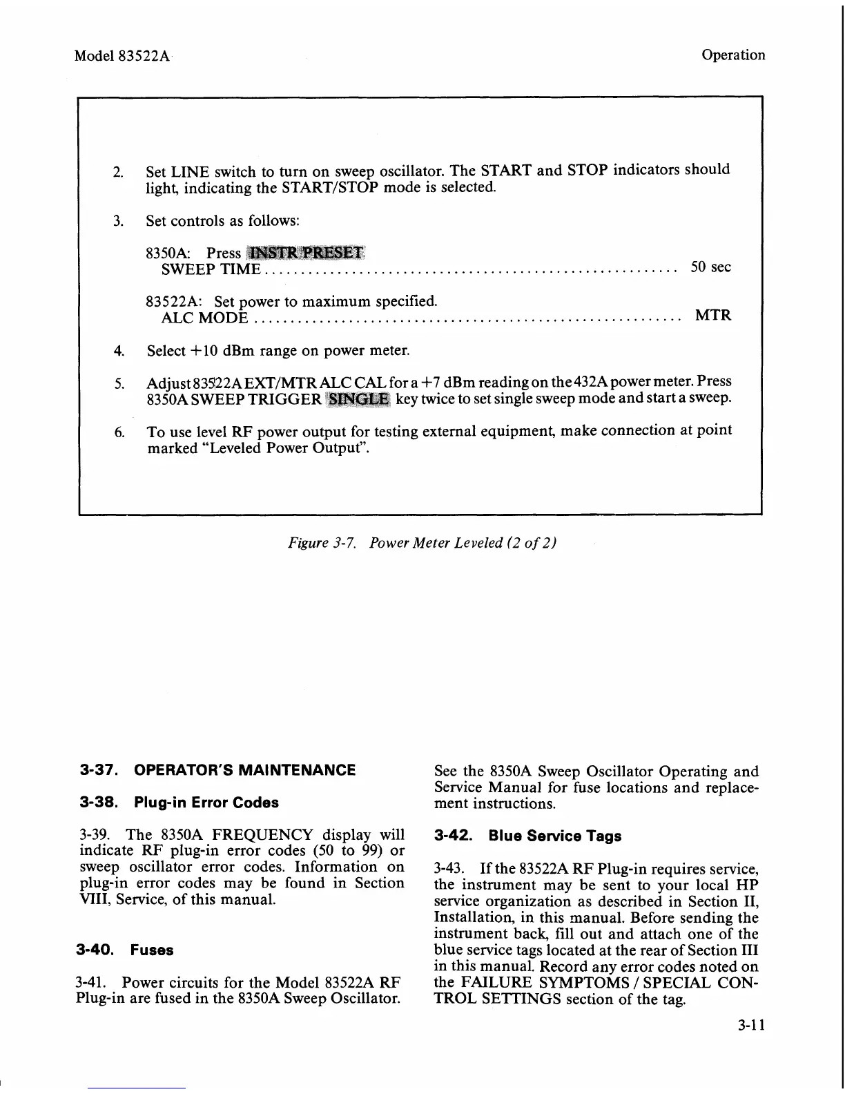
2.
Set LINE switch to turn on sweep oscillator. The START and STOP indicators should
light, indicating the
STARTISTOP mode is selected.
3. Set controls as follows:
..........................................
50 sec
83522A: Set power to maximum specified.
...........................................................
ALC MODE
MTR
4.
Select +10
dBm range on power meter.
5.
Adjust
83422AEXT/MTRALC CAL for a
+7
dBm reading on the432Apower meter. Press
8350A SWEEP TRIGGER
BMaaF3
key twice to set single sweep mode and start a sweep.
6.
To use level
RF
power output for testing external equipment, make connection at point
marked "Leveled Power Output".
Figure
3-7.
Power Meter Leveled
(2
of
2)
3-37. OPERATOR'S MA1 NTENANCE
3-38. Plug-in Error Codes
3-39. The 8350A FREQUENCY display will
indicate RF plug-in error codes
(50
to 99) or
sweep oscillator error codes. Information on
plug-in error codes may be found in Section
VIII, Service, of this manual.
3-40. Fuses
3-41.
Power circuits for the Model
8352211 RF
Plug-in are fused in the
8350A Sweep Oscillator.
See the
8350A Sweep Oscillator Operating and
Service Manual for fuse locations and replace-
ment instructions.
3-42. Blue Service Tags
3-43. If the 83522A RF Plug-in requires service,
the instrument may
be
sent to your local HP
service organization as described in Section
11,
Installation, in this manual. Before sending the
instrument back, fill out and attach one of the
blue service tags located at the rear of Section
I11
in this manual. Record any error codes noted on
the FAILURE SYMPTOMS
/
SPECIAL CON-
TROL SETTINGS section of the tag.