Adjustments Model 83522A
ADJUSTMENTS
-
-
--
-
-
5-23.
POWER METER LEVELING CALIBRATION (Cont'd)
2. Set 83522A
PO'WER
LEVEL,
to +5 dBm. Set power meter
WaE
switch to 0. Adjust
83522A
POWER
LEVEL
,
if necessary, to obtain a meter reading of -5.
3.
Press 83522A
'maG&e
mode. Adjust 83522A front panel
knob to return the
power meter needle to its previous position at -5.
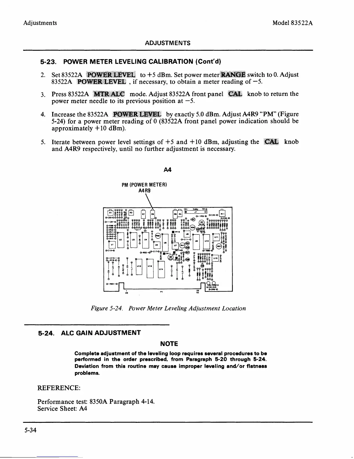
4. Increase the
83522A
by exactly 5.0 dBm. Adjust A4R9 "PM" (Figure
5-24) for a power me
3522A front panel power indication should be
approximately
+
10
dBm).
5. Iterate between power level settings of +5 and +10 dBm, adjusting the
knob
and
A4R9 respectively, until no further adjustment is necessary.
PM
(POWER METER)
A4
R9
Figure
5-24.
Power Meter Leveling Adjustment Location
-
-
-
-
--
-
5-24.
ALC GAIN ADJUSTMENT
NOTE
Complete adjustment of the leveling loop requires several procedures to be
performed in the order prescribed, from Paragraph
5-20
through
5-24.
Deviation from this routine may cause improper leveling andlor flatness
problems.
REFERENCE:
Performance test: 83 50A Paragraph 4- 14.
Service Sheet: A4