Model 83522A Adjustments
ADJUSTMENTS
5-24.
ALC
GAIN
ADJUSTMENT
(Cont'd)
DESCRIPTION:
A4R11, at the inverting input of A4U11, adjusts the gain of the Main ALC Amplifier. A4R11
is adjusted for maximum possible gain without producing oscillations.
EQUIPMENT
Sweep Oscillator
.....................................................
HP 8350A
Oscilloscope..
.......................................................
HP 1740A
Crystal Detector.
......................................................
HP 423A
Power Meter.
.........................................................
HP 432A
Thermistor Mount.
....................................................
HP 478A
Power Splitter.
...........................................
HP 11667A Option 001
10 dB Attenuator
..........................................
HP 8491A Option 010
PROCEDURE:
NOTE
This procedure assumes that
A3S1
is set to the factory-set position (Table
5-6).
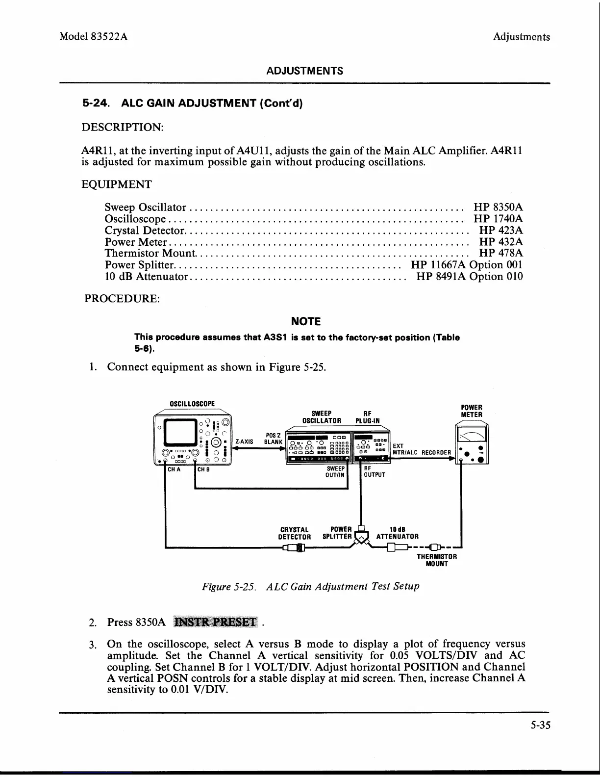
1. Connect equipment as shown in Figure 5-25.
OSCILLATOR PLUG-IN
CRYSTAL POWER
MOUNT
THERMISTOR
Figure
5-25.
ALC
Gain Adjustment Test Setup
2. Press 8350A
3. On the oscilloscope, select A versus B mode to display a plot of frequency versus
amplitude. Set the Channel A vertical sensitivity for 0.05
VOLTS/DIV and AC
coupling. Set Channel
B
for 1 VOLTIDIV. Adjust horizontal POSITION and Channel
A vertical POSN controls for a stable display at mid screen. Then, increase Channel A
sensitivity to 0.01
VIDIV.