Adjustments
Model
83522A
ADJUSTMENTS
5-24.
ALC GAl
N
ADJUSTMENT
(Cont'd)
4. Set the power meter switch to +5 dBm. Note the power meter needle position.
5. On the
835224 press mode.
6. On the
83504 press
7.
If necessary, adjust the output power with the 83522A front panel
control to
needle to the same reading noted in step
crease the
itch by three 5 dB steps to -10 dB. This attenuates the output
22A is now operating at the low end of its calibrated power
range, approximately -2
dBm.
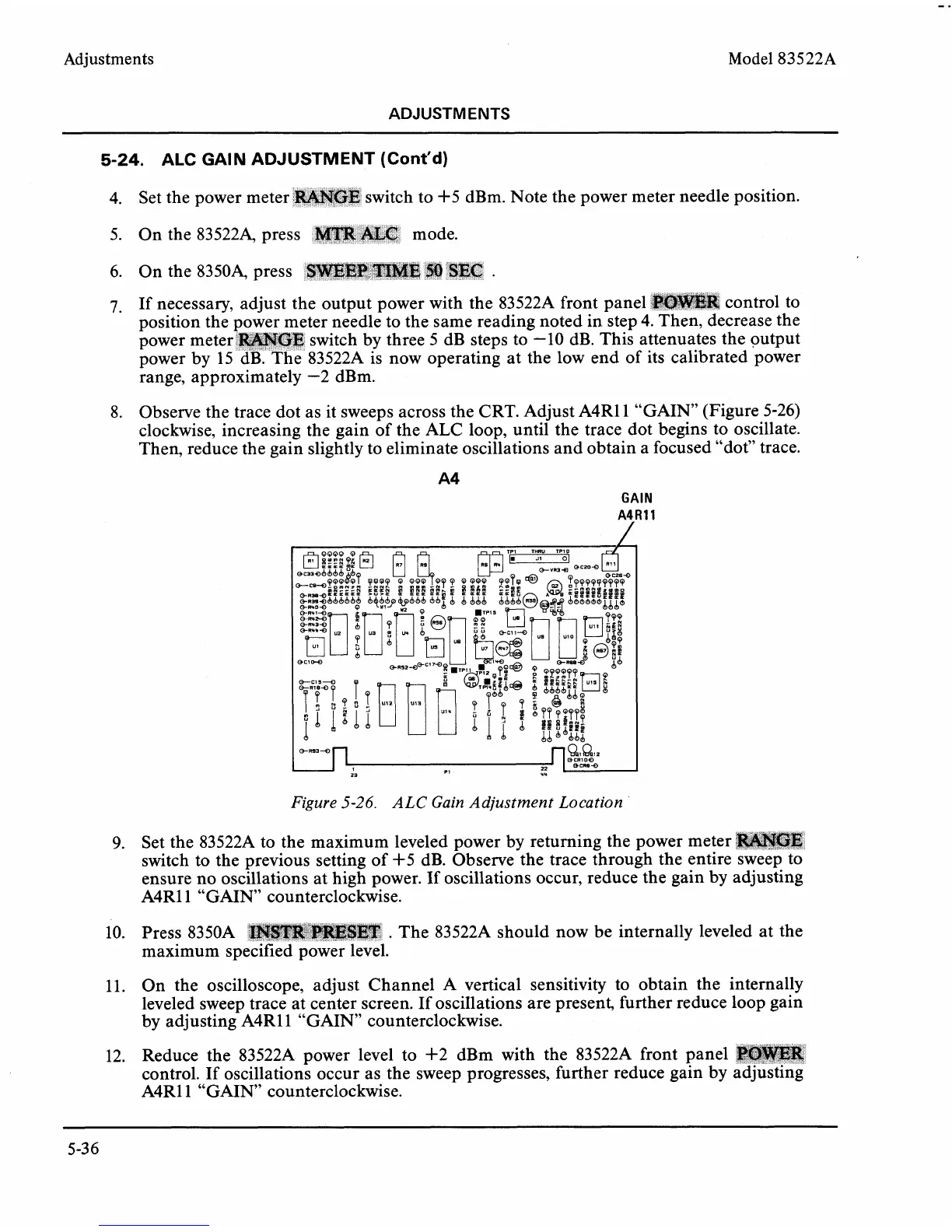
8. Observe the trace dot as it sweeps across the CRT. Adjust A4R11 "GAIN" (Figure 5-26)
clockwise, increasing the gain of the ALC loop, until the trace dot begins to oscillate.
Then, reduce the gain slightly to eliminate oscillations and obtain a focused "dot" trace.
GAIN
A4Rll
/
Set the
switch
ensure
A4R11
Figure
5-26.
ALC Gain Adjustment Location
83522A to the maximum leveled power by returning the power meter
to the previous setting of
+5 dB. Observe the trace through the entire
no oscillations at high power. If oscillations occur, reduce the gain by
"GAIN" counterclockwise.
sweep to
adjusting
10. Press
8350A
.
The 83522A should now be internally leveled at the
11. On the oscilloscope, adjust Channel A vertical sensitivity to obtain the internally
leveled sweep trace at center screen. If
osci1lations are present, further reduce loop gain
by adjusting
A4R11 "GAIN" counterclockwise.
12. Reduce the
83522A power level to +2 dBm with the 83522A front panel
control. If oscillations occur as the sweep progresses, further reduce gain by adjusting
A4R11 "GAIN" counterclockwise.