Model
83522A
Service
oscillator must be installed on A6 in place of the
old resistors. (In some cases, some of the
resistors may be deleted, depending on the drive
requirements of the individual oscillator.)
8-37.
Rear Panel Connector Replacement
8-38. When replacing rear panel connector PI,
connector P2 also must be partially removed to
remove
P1 from the rear panel casting.
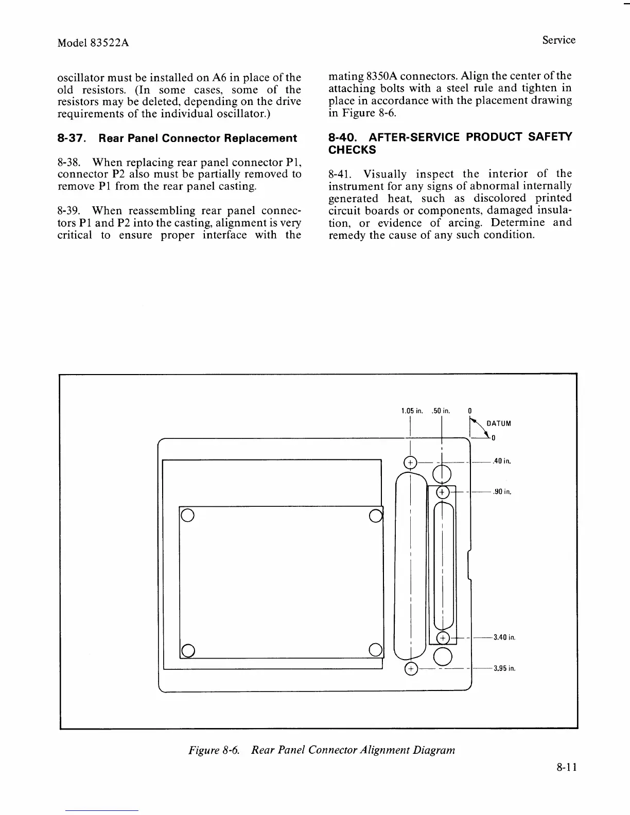
8-39. When reassembling rear panel connec-
tors
P1 and P2 into the casting, alignment is very
critical to ensure proper interface with the
mating
8350A connectors. Align the center of the
attaching bolts with a steel rule and tighten in
place in accordance with the placement drawing
in Figure 8-6.
8-40.
AFTER-SERVICE PRODUCT SAFETY
CHECKS
8-41. Visually inspect the interior of the
instrument for any signs of abnormal internally
generated heat, such as discolored printed
circuit boards or components, damaged insula-
tion, or evidence of arcing. Determine and
remedy the cause of any such condition.
1.05
in.
.50
in. 0
f
,!:'""
-
-
.40 in.
.YO
in.
0
3.40 in.
0
3.95
in.
L
Figure
8-6.
Rear Panel Connector Alignment Diagram